SG505: Difference between revisions
No edit summary |
mNo edit summary |
||
| (7 intermediate revisions by 4 users not shown) | |||
| Line 12: | Line 12: | ||
* [[Media:070-2823-00.pdf|Tektronix SG505 Option 01 Manual]] | * [[Media:070-2823-00.pdf|Tektronix SG505 Option 01 Manual]] | ||
* [[Media:070-4359-00.pdf|Tektronix SG505 Option 02 Manual]] | * [[Media:070-4359-00.pdf|Tektronix SG505 Option 02 Manual]] | ||
* [[Media:Tek sc505 eis | * [[Media:Tek sc505 eis.pdf|Tektronix SG 505 Engineering Instrument Specification]] | ||
}} | }} | ||
Option 01 adds an intermodulation test signal function.<br> | Option 01 adds an intermodulation test signal function.<br> | ||
Option 02 adds a fully balanced output to +28 dBm and selectable source impedance with corresponding changes to the front panel connections. It also includes Option 01. | Option 02 adds a fully balanced output to +28 dBm and selectable source impedance with corresponding changes to the front panel connections. It also includes Option 01. | ||
The SG505 was designed by [[Bruce Hofer]]. | |||
{{BeginSpecs}} | {{BeginSpecs}} | ||
| Line 23: | Line 25: | ||
{{Spec | Output impedance | 600 Ω }} | {{Spec | Output impedance | 600 Ω }} | ||
{{Spec | Distortion | < 0.0008% (−102 dB) from 20 Hz to 20 kHz }} | {{Spec | Distortion | < 0.0008% (−102 dB) from 20 Hz to 20 kHz }} | ||
{{Spec | Sync output | 200 mV<sub>RMS</sub> sine to 20 kHz, at least 120 mV @ 100 kHz; 1 kΩ source impedance }} | {{Spec | Sync output | 200 mV<sub>RMS</sub> sine to 20 kHz, at least 120 mV @ 100 kHz; 1 kΩ source impedance; referenced to chassis ground }} | ||
{{Spec | Opt. 1 Intermododulation Signal | {{Spec | Options | | ||
* Opt.1 Intermododulation Signal – Regular output signal superimposed with 60 Hz or 250 Hz low frequency signal with 4:1 amplitude ratio | |||
* Opt.2 Balanced output with selectable source impedance (50, 150, or 600 Ω) | |||
}} | |||
{{EndSpecs}} | {{EndSpecs}} | ||
== | ==Links== | ||
* [https://www.paulvdiyblogs.net/2025/03/diy-build-of-tek-sg505.html DIY Build of the Tek SG505 Oscillator] @ Paul V's DIY Electronics blog | |||
{{Documents|Link=SG505}} | {{Documents|Link=SG505}} | ||
{{PatentLinks|SG505}} | |||
==Internals== | ==Internals== | ||
The SG505 uses a state-variable oscillator topology employing NE5534 opamps and an N-FET (151-1021-00) based AGC. Range switches change capacitors and AGC time constants, the main dial changes the integrator resistor. | The SG505 uses a state-variable oscillator topology employing NE5534 opamps and an N-FET (151-1021-00) based AGC. | ||
Range switches change capacitors and AGC time constants, the main dial changes the integrator resistor. | |||
The SG505 is floating with respect to the chassis (up to 30 V) but can be grounded via a front-panel switch. | |||
The power supply uses the two floating 25 V<sub>AC</sub> windings from the mainframe, and the mainframe's pass transistors, to produce ±15 V. | |||
The sync output is always referenced to chassis ground, which is done via a linear optocoupler circuit. | |||
===Rear interface=== | |||
* Buffered output: | |||
** Base or Opt.1: 25A , common 26A (electrically connected to front panel output common). Unity gain buffered version of the actual output signal from front panel connector, THD typ. <0.03%, 600 Ω source impedance. Load must be ≥1 kΩ to prevent degradation in oscillator distortion at the front panel. | |||
** Opt. 2: 25A is inverted from + output, 26A inverted from – output. Signal is attenuated 20 dB and buffered from the actual output signal at the front panel connector. | |||
* Sync output: | |||
** 27B, ground on 28B. Approximately 200 mV<sub>RMS</sub> sine wave identical to front panel SYNC output signal; 50 Ω source impedance, always ground referenced | |||
==See Also== | ==See Also== | ||
* [[F7523A1]] | * [[F7523A1]] | ||
* [https://www.youtube.com/watch?v=c2uHdtpm1mA Zenwizard Studios - | * [https://www.youtube.com/watch?v=c2uHdtpm1mA Zenwizard Studios - Tektronix SG505 Repair and Abridged Validation] | ||
* [https://www.youtube.com/watch?v=3uB28MuskGw Zenwizard Studios - FINALLY Measuring the Distortion of an SG505!] | * [https://www.youtube.com/watch?v=3uB28MuskGw Zenwizard Studios - FINALLY Measuring the Distortion of an SG505!] | ||
* [https://www.youtube.com/watch?v=QgIAB0WrqnY Zenwizard Studios - SG505 Op1 Restoration and Distortion Measurements] | |||
==Prices== | ==Prices== | ||
| Line 49: | Line 68: | ||
| align="right" | $600 | | align="right" | $600 | ||
|- | |- | ||
! In | ! In 2025 Dollars | ||
| align="right" | $2, | | align="right" | $2,300 | ||
|} | |} | ||
Latest revision as of 08:39, 29 March 2025
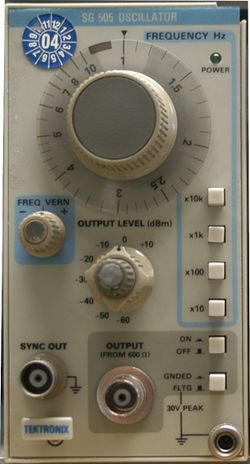
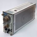
The Tektronix SG505 is an ultra-low distortion oscillator plug-in for the TM500 system.
Option 01 adds an intermodulation test signal function.
Option 02 adds a fully balanced output to +28 dBm and selectable source impedance with corresponding changes to the front panel connections. It also includes Option 01.
The SG505 was designed by Bruce Hofer.
Key Specifications
| Frequency range | 10 Hz to 100 kHz nom. (typ. 9 Hz to 110 kHz) in four overlapping ranges |
|---|---|
| Frequency accuracy | 3% of dial reading |
| Output level | +10 dBm to −60 dBm into 600 Ω in eight 10 dB steps, plus variable control +2.2 dB to −10 dB from calibrated position |
| Output impedance | 600 Ω |
| Distortion | < 0.0008% (−102 dB) from 20 Hz to 20 kHz |
| Sync output | 200 mVRMS sine to 20 kHz, at least 120 mV @ 100 kHz; 1 kΩ source impedance; referenced to chassis ground |
| Options |
|
Links
- DIY Build of the Tek SG505 Oscillator @ Paul V's DIY Electronics blog
Documents Referencing SG505
| Document | Class | Title | Authors | Year | Links |
|---|---|---|---|---|---|
| Tekscope 1980 V12 N1.pdf | Article | New Products | 1980 | 308 • SG505 • 8002A | |
| Tekscope 1980 V12 N2.pdf | Article | New Products | 1980 | 7854 • 468 • AA501 • SG505 • CG551AP • 1900 • 7612D | |
| Tekscope 1980 V12 N3.pdf | Article | Automatic Distortion Analyzer Speeds Distortion Measurements | Bruce Hofer | 1980 | AA501 • SG505 |
| 070-2088-04.pdf | Book | TM500 Series Rear Interface Data Book | 1985 | AA501 • AF501 • AM501 • AM502 • AM503 • AM511 • DC501 • DC502 • DC503 • DC503A • DC504 • DC505 • DC505A • DC508 • DC508A • DC509 • DC510 • DC5009 • DC5010 • DD501 • DL502 • DM501 • DM501A • DM502 • DM502A • DM505 • DM5010 • FG501 • FG501A • FG502 • FG503 • FG504 • FG507 • FG5010 • LA501 • LA501W • WR501 • MR501 • PG501 • PG502 • PG505 • PG506 • PG507 • PG508 • PS501 • PS502 • PS503 • PS503A • PS505 • PS5010 • RG501 • SC501 • SC502 • SC503 • SC504 • SG502 • SG503 • SG504 • SG505 • SW503 • TG501 • TR501 • TR502 • MI5010 • MX5010 • SI5010 |
Patents that may apply to SG505
| Page | Title | Inventors | Filing date | Grant date | Links |
|---|---|---|---|---|---|
| Patent US 4560958A | State variable oscillator having improved rejection of leveler-induced distortion | Bruce Hofer | 1984-02-24 | 1985-12-24 | SG505 |
Internals
The SG505 uses a state-variable oscillator topology employing NE5534 opamps and an N-FET (151-1021-00) based AGC. Range switches change capacitors and AGC time constants, the main dial changes the integrator resistor.
The SG505 is floating with respect to the chassis (up to 30 V) but can be grounded via a front-panel switch. The power supply uses the two floating 25 VAC windings from the mainframe, and the mainframe's pass transistors, to produce ±15 V.
The sync output is always referenced to chassis ground, which is done via a linear optocoupler circuit.
Rear interface
- Buffered output:
- Base or Opt.1: 25A , common 26A (electrically connected to front panel output common). Unity gain buffered version of the actual output signal from front panel connector, THD typ. <0.03%, 600 Ω source impedance. Load must be ≥1 kΩ to prevent degradation in oscillator distortion at the front panel.
- Opt. 2: 25A is inverted from + output, 26A inverted from – output. Signal is attenuated 20 dB and buffered from the actual output signal at the front panel connector.
- Sync output:
- 27B, ground on 28B. Approximately 200 mVRMS sine wave identical to front panel SYNC output signal; 50 Ω source impedance, always ground referenced
See Also
- F7523A1
- Zenwizard Studios - Tektronix SG505 Repair and Abridged Validation
- Zenwizard Studios - FINALLY Measuring the Distortion of an SG505!
- Zenwizard Studios - SG505 Op1 Restoration and Distortion Measurements
Prices
| Year | 1980 |
|---|---|
| Catalog Price | $600 |
| In 2025 Dollars | $2,300 |
Pictures
-
Front Panel
-
Front Panel
-
Right Side Internal
-
Left Side Internal
-
PCB Right Side
-
PCB Left Side
-
PCB Left Side Detail
-
Option 2 3/4 View
-
Option 2 Front Panel
-
Option 2 Left Internal
-
Option 2 Right Internal


