647A: Difference between revisions
No edit summary |
No edit summary |
||
| (23 intermediate revisions by 4 users not shown) | |||
| Line 1: | Line 1: | ||
{{Oscilloscope Sidebar | | {{Oscilloscope Sidebar | ||
|manufacturer=Tektronix | |||
summary=100 MHz scope | | |series=647 | ||
image=Tek 647a trace5.jpg| | |model=647A | ||
caption=647A front view | | |summary=100 MHz scope | ||
introduced=1967 | | |image=Tek 647a trace5.jpg | ||
discontinued=1974 | | |caption=647A front view | ||
manuals= | |introduced=1967 | ||
* [ | |discontinued=1974 | ||
|designers= | |||
|manuals= | |||
* [[Media:070-0614-00.pdf|Tek 647A Instruction Manual]]<br /><small>Alternate: [https://bama.edebris.com/download/tek/647a/tek%20647a.djvu DjVu @ BAMA]</small> | |||
* ''[[Media:070-0627-00.pdf|R647A Manual 070-0627-00 needed]]'' | |||
* [[Media:Tek 647a fcp feb 1967.pdf|Tektronix 647A Factory Calibration Procedure, February 1967]] | |||
* [[Media:Tek 647a cal outline.pdf|Tektronix Type 647 and 647A Calibration Outline]] (OCR) | |||
}} | }} | ||
The '''Tektronix 647A''' is an improved version of the [[647]], with the main enhancement being doubling the bandwidth to 100 MHz. | The '''Tektronix 647A''' is an improved version of the [[647]], with the main enhancement being doubling the bandwidth to 100 MHz. | ||
Tek also introduced | Tek also introduced two new plug-ins with the 647A. | ||
The [[10A2A]] is an improved version of the dual channel [[10A2]] vertical plug-in, with bandwidth extended to 100 MHz. | |||
The [[11B2A]] is similar to the [[11B2]] dual time base, but triggers up to 100 MHz. | |||
The [[10A1]] differential comparator amplifier, first introduced in 1965 for the [[647]], has a maximum bandwidth of 55 MHz for sensitivities of 5 mV/div and higher in the 647A. | |||
It operates down to 1 mV/div sensitivity, and includes a comparison voltage mode with a calibrated DC offset similar to that first offered in the [[W|type W]] plug-in. | |||
In total, only | In total, only six plug-ins were developed for the 647 series – the generic dual trace vertical [[10A2]] and [[10A2A]] amplifiers, | ||
a differential comparator vertical [[10A1]] amplifier, and a single [[11B1]] and dual [[11B2]] and [[11B2A]] time bases. | |||
Although it combined high performance with rugged reliability and compactness, the 647 series was one of Tek’s “orphan” scope series, a result of when it was introduced. | |||
By the time the 100 MHz 647A was announced, the majority of the R&D effort at Tek was devoted to the [[7000-series scopes|7000 series]], which introduced just two years later, in 1969. | |||
The entry level 7000 series mainframe started with performance nearly the same as the top of the line 647A. | |||
With on-screen scale factor read-out, and even more compact form factor, 7000 would offer many advantages over any of Tek’s existing lines of scopes. | |||
When the work on developing plug-ins for 7000 series was ramping up, no additional plug-ins for any of the “legacy” plug-in scopes would be developed. | |||
For the 530/540/550 series which started over 20 years earlier, a large family of plug-ins were available, but for scopes which were introduced in the mid 1960s, the variety of plug-ins was very limited. | |||
The [[067-0544-00]] is a calibration plug-in for the 647A. | The [[067-0544-00]] is a calibration plug-in for the 647A. | ||
{{ | {{BeginSpecs}} | ||
{{Spec | Bandwidth | DC to 100 MHz (≤ 3 dB) with [[10A2A|10A2A plug-in]] }} | |||
{{Spec | Rise time | 3.5 ns }} | |||
{{Spec | CRT | [[T6470]], P31 std / P11 opt., 6 cm × 10 cm, 14 kV acceleration }} | |||
{{Spec | Power | 108/115/122/216/235/244 V<sub>AC</sub> ±10%,selected via primary voltage selector and voltage range selector switches, 50 Hz to 60 Hz; 185W with [[10A2]] & [[11B2]] plug-in }} | |||
{{Spec | Operating Temperature | –30 C° to +65 C°}} | |||
{{Spec | Cooling | AC Fan (only in rack variant) }} | |||
{{Spec | Thermal Protection | Automatic resetting thermal cutout, in case internal temperature exceeds safe operating level }} | |||
{{Spec | Weight | 18.4 kg (40.5 lbs) }} | |||
{{EndSpecs}} | |||
==Links== | |||
{{Documents|Link=647A}} | |||
{{PatentLinks|647A}} | |||
==Internals== | ==Internals== | ||
The vertical amplifier contained in the 647A indicator unit (mainframe) consists of NPN and PNP bipolar transistors. The output transistors, Q484 and Q494, are selected [[2N3866]] NPN transistors. The datasheet for the 2N3866 lists Its transit frequency as 800 MHz and specifies an absolute maximum value of Vceo of 30 V. The quiescent value of Vce on Q484 and Q494 is about 30 V. So it seems likely that the selection process for these transistors involved testing their performance at the high end of their specified voltage range, and probably beyond. | The vertical amplifier contained in the 647A indicator unit (mainframe) consists of NPN and PNP bipolar transistors. | ||
The output transistors, Q484 and Q494, are selected [[2N3866]] NPN transistors. | |||
The datasheet for the 2N3866 lists Its transit frequency as 800 MHz and specifies an absolute maximum value of Vceo of 30 V. | |||
The quiescent value of Vce on Q484 and Q494 is about 30 V. | |||
So it seems likely that the selection process for these transistors involved testing their performance | |||
at the high end of their specified voltage range, and probably beyond. | |||
The power supply of the 647A is all solid state, with a zener voltage reference and NPN pass transistors. The horizontal amplifier in the 647A uses selected [[2N3119]] NPN bipolar transistors for the output. These are specified as having a transit frequency of 250 MHz and a | The power supply of the 647A is all solid state, with a zener voltage reference and NPN pass transistors. | ||
The horizontal amplifier in the 647A uses selected [[2N3119]] NPN bipolar transistors for the output. | |||
These are specified as having a transit frequency of 250 MHz and a V<sub>CEO</sub> max of 80 V. | |||
==Related== | ==Related== | ||
| Line 56: | Line 93: | ||
Tek 647a disp2.jpg | Tek 647a disp2.jpg | ||
Tek 647a disp1.jpg | Tek 647a disp1.jpg | ||
Tek 647a 10a2a 11b2a.jpg|647A with [[10A2A]] and [[11B2A]] | |||
</gallery> | |||
'''R647A''' | |||
<gallery> | |||
Tek r647a.jpg|R647A front view | |||
Tek r647a inside.jpg|RM647 inside view | |||
Sideways r647a.jpg|Special R647A for US Air Force | |||
Sideways r647a rear.jpg|Rear panel of the Air Force R647A | |||
</gallery> | </gallery> | ||
==Components== | |||
{{Parts|647A}} | |||
[[Category:647 series scopes]] | [[Category:647 series scopes]] | ||
Revision as of 12:36, 12 July 2024
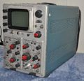
The Tektronix 647A is an improved version of the 647, with the main enhancement being doubling the bandwidth to 100 MHz.
Tek also introduced two new plug-ins with the 647A. The 10A2A is an improved version of the dual channel 10A2 vertical plug-in, with bandwidth extended to 100 MHz. The 11B2A is similar to the 11B2 dual time base, but triggers up to 100 MHz. The 10A1 differential comparator amplifier, first introduced in 1965 for the 647, has a maximum bandwidth of 55 MHz for sensitivities of 5 mV/div and higher in the 647A. It operates down to 1 mV/div sensitivity, and includes a comparison voltage mode with a calibrated DC offset similar to that first offered in the type W plug-in.
In total, only six plug-ins were developed for the 647 series – the generic dual trace vertical 10A2 and 10A2A amplifiers, a differential comparator vertical 10A1 amplifier, and a single 11B1 and dual 11B2 and 11B2A time bases. Although it combined high performance with rugged reliability and compactness, the 647 series was one of Tek’s “orphan” scope series, a result of when it was introduced. By the time the 100 MHz 647A was announced, the majority of the R&D effort at Tek was devoted to the 7000 series, which introduced just two years later, in 1969.
The entry level 7000 series mainframe started with performance nearly the same as the top of the line 647A. With on-screen scale factor read-out, and even more compact form factor, 7000 would offer many advantages over any of Tek’s existing lines of scopes. When the work on developing plug-ins for 7000 series was ramping up, no additional plug-ins for any of the “legacy” plug-in scopes would be developed. For the 530/540/550 series which started over 20 years earlier, a large family of plug-ins were available, but for scopes which were introduced in the mid 1960s, the variety of plug-ins was very limited.
The 067-0544-00 is a calibration plug-in for the 647A.
Key Specifications
| Bandwidth | DC to 100 MHz (≤ 3 dB) with 10A2A plug-in |
|---|---|
| Rise time | 3.5 ns |
| CRT | T6470, P31 std / P11 opt., 6 cm × 10 cm, 14 kV acceleration |
| Power | 108/115/122/216/235/244 VAC ±10%,selected via primary voltage selector and voltage range selector switches, 50 Hz to 60 Hz; 185W with 10A2 & 11B2 plug-in |
| Operating Temperature | –30 C° to +65 C° |
| Cooling | AC Fan (only in rack variant) |
| Thermal Protection | Automatic resetting thermal cutout, in case internal temperature exceeds safe operating level |
| Weight | 18.4 kg (40.5 lbs) |
Links
Documents Referencing 647A
| Document | Class | Title | Authors | Year | Links |
|---|---|---|---|---|---|
| Service Scope 43 Apr 1967.pdf | Article | New From Tektronix, Inc. In 1967 | 1967 | 568 • 230 • 454 • 647A • C-40 • 1A4 • 1A5 • 3L5 • 200-1 |
Patents that may apply to 647A
| Page | Title | Inventors | Filing date | Grant date | Links |
|---|---|---|---|---|---|
| Patent US 3453403A | Power selection device | Eldon Hoffman | 1966-08-18 | 1969-07-01 | 115 • 140 • 141 • 141A • 144 • 145 • 146 • 147 • 148 • 149 • 149A • 230 • 284 • 286 • 453 • 454 • 491 • 520A • 521A • 522 • 545B • 547 • 556 • 561B • 564B • 568 • 576 • 611 • 647A • 2101 • 2601 • 5030 • R5030 • 5031 • R5031 • 7503 • 7504 • 7704 • 7704A • 7904 • R7903 |
Internals
The vertical amplifier contained in the 647A indicator unit (mainframe) consists of NPN and PNP bipolar transistors. The output transistors, Q484 and Q494, are selected 2N3866 NPN transistors. The datasheet for the 2N3866 lists Its transit frequency as 800 MHz and specifies an absolute maximum value of Vceo of 30 V. The quiescent value of Vce on Q484 and Q494 is about 30 V. So it seems likely that the selection process for these transistors involved testing their performance at the high end of their specified voltage range, and probably beyond.
The power supply of the 647A is all solid state, with a zener voltage reference and NPN pass transistors. The horizontal amplifier in the 647A uses selected 2N3119 NPN bipolar transistors for the output. These are specified as having a transit frequency of 250 MHz and a VCEO max of 80 V.
Related
The Hungarian company Elektronikus Mérőkészülékek Gyára (EMG) produced a clone of 647A, the TR-4653, in the 1970s.
Pictures
-
647A front view
-
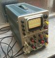
647A left view
-
647A right view
-
647A rear view
-
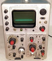
R647A front view
-
R647 inside view
-
Special R647A for US Air Force
-
Rear panel of the Air Force R647A
-
-
-
-
-
-
-
-
-
-
-
-
-
-
-
-
R647A
-
R647A front view
-
RM647 inside view
-
Special R647A for US Air Force
-
Rear panel of the Air Force R647A
Components
Some Parts Used in the 647A
| Part | Part Number(s) | Class | Description | Used in |
|---|---|---|---|---|
| 2N3119 | 151-0124-00 | Discrete component | NPN VHF power transistor | 647A |
| 2N3866 | 151-0211-00 | Discrete component | NPN VHF power transistor | 647A |
| 5642 | 154-0051-00 • 154-0079-00 | Vacuum Tube (Diode) | directly-heated high-voltage rectifier | 310 • 310A • 316 • 317 • 360 • 453 • 502 • 502A • 503 • 504 • 506 • 513 • 515 • 516 • 524 • 529 • RM529 • 533 • 533A • 535 • 536 • 543 • 543A • 543B • 545 • 545A • 545B • 547 • 551 • 555 • 556 • 560 • 561 • 561A • 561S • 564 • 567 • 570 • 575 • 581 • 581A • 585 • 585A • 647 • 647A |
| T6470 | 154-0434-00 • 154-0448-00 | CRT | CRT | 647 • 647A |


