7A12: Difference between revisions
(Added additional picture) |
No edit summary |
||
| Line 10: | Line 10: | ||
|designers=Roy Hayes | |designers=Roy Hayes | ||
|manuals= | |manuals= | ||
* [[Media:070-0977-01.pdf|Tektronix 7A12 Manual]] ( | * [[Media:070-0977-01.pdf|Tektronix 7A12 Manual]] (OCR) | ||
<small> | |||
'''Alternate''' | |||
* [http://bama.edebris.com/download/tek/7a12/tek-7a12.pdf Tektronix 7A12 Manual @ BAMA] (PDF) | * [http://bama.edebris.com/download/tek/7a12/tek-7a12.pdf Tektronix 7A12 Manual @ BAMA] (PDF) | ||
</small> | |||
}} | }} | ||
The '''Tektronix 7A12''' is a 120 MHz dual-trace vertical plug-in for [[7000-series scopes]]. This original 7000-series plugin allows to compensate large dc offset voltages, however the offset voltage is not available on the front panel to be measured externally as with the [[7A11]]. | The '''Tektronix 7A12''' is a 120 MHz dual-trace vertical plug-in for [[7000-series scopes]]. This original 7000-series plugin allows to compensate large dc offset voltages, however the offset voltage is not available on the front panel to be measured externally as with the [[7A11]]. | ||
| Line 33: | Line 36: | ||
==Links== | ==Links== | ||
* [ | * [https://www.amplifier.cd/Test_Equipment/Tektronix/Tektronix_7000_series_amplifier/amplifier_7A12.htm 7A12 page @ amplifier.cd] | ||
* [http://www.barrytech.com/tektronix/tek7000/tek7a12.html 7A12 page @ barrytech.com] | * [http://www.barrytech.com/tektronix/tek7000/tek7a12.html 7A12 page @ barrytech.com] | ||
| Line 46: | Line 49: | ||
</gallery> | </gallery> | ||
{{ | ==Components== | ||
{{Parts|7A12}} | |||
[[Category:7000 series vertical plugins]] | [[Category:7000 series vertical plugins]] | ||
Revision as of 13:56, 6 October 2023

The Tektronix 7A12 is a 120 MHz dual-trace vertical plug-in for 7000-series scopes. This original 7000-series plugin allows to compensate large dc offset voltages, however the offset voltage is not available on the front panel to be measured externally as with the 7A11.
Switches on the front panel control miniature relays in the signal path, such as those selecting input attenuators, through logic circuits. It uses the 155-0032-00 as a gain stage and the 155-0022-00 for channel switching.
The 7A12 was designed by Roy Hayes (who also designed the 3A3 and 3A8 before leaving for HP Loveland in Jan 1971). The Evaluation Engineer for the 7A12 was Peter Starič, co-author of the book "Wideband Amplifiers" with Erik Margan.
Key Specifications
| Bandwidth | 120 MHz (79xx) / 105 MHz (77xx) / 55 MHz (74xx) |
|---|---|
| Deflection | 5 mV/Div to 5 V/Div (1–2–5), variable up to 12.5 V/Div |
| Input impedance | 1 MΩ // 24 pF |
| Timing | Delay difference between channels < 500 ps |
| Channel isolation | At least 3000:1 at 75 MHz |
| Maximum input | 350 V DC + Peak AC at 1 kHz or less |
| DC offset | At least ±500 divisions |
Links
Pictures
-
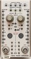
Front view
-
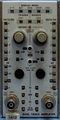
Front view
-
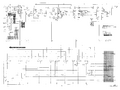
Attenuator schematic with relays
-
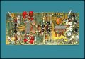
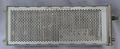
7A12 Amplifier PCB
-
Left side view


Components
Some Parts Used in the 7A12
| Part | Part Number(s) | Class | Description | Used in |
|---|---|---|---|---|
| 148-0034-01 | 148-0034-01 | Discrete component | miniature DPDT relay | 485 • 7A12 |
| 148-0034-02 | 148-0034-02 | Discrete component | miniature DPDT relay | 7A12 |
| 155-0022-00 | 155-0022-00 • 155-0022-01 | Monolithic integrated circuit | analog multiplexer | 147 • 148 • 149 • 335 • 468 • 1430 • 1441 • 1461 • 1900 • 1910 • 2220 • 2221 • 2230 • 5223 • 5403 • 5440 • 5441 • 5443 • 5444 • 5A38 • 7313 • 7403N • 7503 • 7504 • 7514 • 7603 • AN/USM-281C • 7613 • 7623 • 7623A • 7633 • 7704 • R7704 • 7704A • 7834 • 7844 • 7854 • R7912 • 7912AD • 7912HB • 7904 • R7903 • 7904A • 7934 • 7A12 • 7A18 • 7A18A • 7A18N • 7B52 • 7B53N • 7D10 • 7D11 • 7D12 • NT-7000 • P7001 |
| 155-0032-00 | 155-0032-00 • 155-0032-01 | Monolithic integrated circuit | variable-gain transconductance (current output with voltage input) amplifier | 335 • 464 • 465 • 465B • 466 • 475 • 475A • 475M • 634 • 650 • 651 • 652 • 653 • 655 • 656 • 670 • 671 • 7A12 • 475 • FG504 • 1440 • 1460 • 1480 • 1481 • 1482 • 1485 |