160
The Tektronix 160 series is a modular instrument system designed to generate timed pulses of variable amplitude and width for use in nerve stimulation/neurophysical experiments. It was designed by Dick Ropiequet and made from 1952 until at least 1970 (appearing in the catalog for that year but not subsequent years, though limited production may have continued).
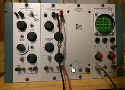
A 160 series system typically includes a Type 160 or 160A power supply, a Type 360 indicator unit, and one or more of the 161, 162, and 163 trigger and sweep modules. There is also a single-unit power supply, the 126. The height of each module is 7U (seven rack units), and they can be installed in the FA 160 mounting frame.
Each module is the size of a small shoe box. Power connections are made behind the modules using Type W160 cables that have octal connectors. The power cables can be connected in a star topology (Type 160 in the center) or can be daisy-chained using the loop-through connection on the back of each module. (The Type 122 amplifier modules that also use octal power connectors are not compatible as they use quite different voltages.)
Signal connections are made on the front, typically with banana plugs.
In a typical setup, the input signal is fed through a splitter to the Y-input of the 360 and the trigger input of the 161. The 161 generates a trigger pulse that controls a 162, which generates the horizontal ramp for the sweep. This ramp signal is sent to the 360 horizontal input.
The signals on the front panel of the 160-series modules are all single-ended.
According to the May 1952 issue of Tek Talk (page 6), the 160 Series entered limited production in April of 1952.
Key Specifications
| +300 V output | DC, unregulated, 170 mA (160A: 250 mA) max |
|---|---|
| +225 V output | DC, regulated, 125 mA (160A: 175 mA) max |
| +150 V output | DC, regulated, 5 mA (160A: 15 mA) max |
| −170 V output | DC, regulated, 125 mA max |
| 6.3 V output | AC, unregulated, 10 (160A: 20 A) A max |
| +70 V output | 160A only; DC, unregulated max load? |
Links
Documents Referencing 160
- (no results)
Documents Referencing 160A
- (no results)
Internals
The 160A and 163 use the ceramic strip and silver-bearing solder construction style that is prevalent in other Tektronix equipment of the era, such as the 500-series scopes like the 545. The 160, 161, and 162 utilize point-to-point construction with bus wiring rather than ceramic strips.
The Type 360 indicator unit contains the CRT HV power supply and the vertical amplifier. It was initially constructed using a printed circuit board, but later changed back to ceramic strips when it was discovered that the early double-sided PCB process that used riveted eyelets proved to be unreliable due to thermal expansion and oxidation issues. (The 310 had the same problem.)
The 360 uses a standard 3WP series 3-inch CRT, with a phase splitter to generate the differential drive for the horizontal deflection plates. The cathode voltage is −1850 V. No post-deflection acceleration is used.
The 160 power supply was produced with serial numbers 101-619. For serial numbers 620 and up, it is slightly different and is called the 160A.
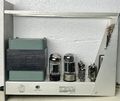
The 160 and 160A both use a 5V4 rectifier tube for the negative voltage, and two 5V4 tubes in parallel (5V4/V8 added in parallel from SN > 324) for the positive voltage. The 5V4s were replaced with 5AR4 from SN 10250. Both use 5651 87-volt reference tubes.
The 160 and 160A differ in their output regulator circuits. The 160 uses a 6AS7 dual-triode tube, one half to regulate the +225 V output, and the other half to regulate the −170 V. The 160A uses both halves of a 6080 dual triode in parallel to regulate the +225 V output, and two parallel 12B4 triodes to regulate the −170 V.
Pictures
160
-
160 front, SN 307
-
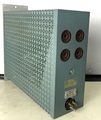
160 side
-
160 top, showing two 5V4 rectifiers
-
160 rear
-
160 bottom
-
160 schematic
-
160 introduction in TekTalk May 1952
160A
-
160A Power supply, front
-
160A Power supply
-
160A Power supply
-
160A Power supply, rear
-
160A Power supply, right
-
160A Power supply, underside
-
160A schematic
Instruments
-
Frame with 162, 161, 163, and 160A (photo courtesy of Dave Nicol)
-
Frame with 162, 161, 163, and 160A, rear view (photo courtesy of Dave Nicol)
-
160 system in operation
-
-
-
-
-
-
-
-
Components
Some Parts Used in the 160
| Part | Part Number(s) | Class | Description | Used in |
|---|---|---|---|---|
| 120-0054-00 | 120-0054-00 | Discrete component | power transformer | 160 |
| 12AU7 | 154-041 • 154-0041-00 • 154-0287-00 | Vacuum Tube (Dual Triode) | dual medium-μ triode | 104 • 104A • 122 • 160 • 161 • 162 • 181 • 190 • 310 • 310A • 316 • 317 • 3C66 • 502 • 502A • 507 • 511A • 512 • 516 • 517 • 517A • 524 • 526 • 535 • 536 • 545 • 545A • 545B • 547 • 549 • 555 • 561 • 564 • 570 • 575 • 581 • 581A • 585 • 585A • C • D • E • N • Q • Hickok 1825 |
| 5651 | 154-052 • 154-0052-00 • 154-0288-00 | Gas Discharge Tube (Voltage regulator) | 87 V voltage reference | 128 • 160 • 310 • 310A • 502 • 503 • 504 • 511A • 512 • 516 • 517 • 524 • 526 • 531 • 531A • 535 • 536 • 541 • 541A • 543 • 543A • 543B • 545 • 545A • 545B • 570 • 549 • 581 • 581A • 585 • 585A |
| 5AR4 | 154-0168-00 | Vacuum Tube (Dual Rectifier) | dual rectifier | 502 • 502A • 160 |
| 5V4G | 154-008 • 154-0008-00 | Vacuum Tube (Dual Rectifier) | dual rectifier | 104 • 104A • 160 • 511A • 514 |
| 6080 | 154-0056-00 • 154-0315-00 | Vacuum Tube (Dual Triode) | dual power triode | 132 • 160 • 316 • 317 • 516 • 535 • 535A • RM35A • 541 • 541A • 535 • 536 • 545 • 545A • 545B • 546 • 547 • 549 • 565 • 567 • 575 • 581 • 581A • 585 • 585A |
| 6AS7 | 154-020 • 154-0020-00 | Vacuum Tube (Pentode) | dual power triode | 160 • 506 • 511A • 512 • 513 • 517 • 517A • 524 • 561 • 561A • 561S • 564 |
| 6AU6 | 154-0022-00 • 157-0073-00 • 157-0059-00 • 154-0284-00 | Vacuum Tube (Pentode) | RF pentode | 107 • 160 • 181 • 190 • 60 • 2A60 • 72 • 3A72 • 3C66 • 310 • 310A • 316 • 317 • 360 • 502 • 502A • 506 • 511 • 511A • 512 • 513 • 516 • 517 • 517A • 524 • 526 • 529 • RM529 • 531 • 531A • 535 • 536 • 545 • 545A • 546 • 547 • 549 • 555 • 561 • 561A • 561S • 564 • 565 • 567 • 570 • 575 • 581 • 581A • 585 • 585A • 80 • C • CA • Q |
| 6AW8 | 154-0095-00 | Vacuum Tube (Triode/Pentode) | triode-pentode combo | 132 • 160 • 541 • 535 • 545 |
| 6U8 | 154-0033-00 | Vacuum Tube (Triode/Pentode) | triode-pentode combo | 130 • 160 • 163 • 310 • 315 • 316 • 524 • 535 • 545 • T |


