7704: Difference between revisions
(year) |
No edit summary |
||
| (49 intermediate revisions by 6 users not shown) | |||
| Line 1: | Line 1: | ||
{{Oscilloscope Sidebar| | {{Oscilloscope Sidebar | ||
|manufacturer=Tektronix | |||
image= | |series=7000-series scopes | ||
caption= | |model=7704 | ||
|summary=150 MHz non-storage mainframe | |||
|image=7704-front.jpg | |||
manuals= | |caption=Tek 7704 (non-A) CRT and controls | ||
* [ | |introduced=1969 | ||
|discontinued=1972 | |||
|designers=Gene Andrews;Bob Shand; | |||
|manuals= | |||
'''7704''' | |||
* [[Media:070-0981-00.pdf|Tektronix 7704 Manual, 1970]] (OCR) | |||
* [[Media:070-0981-00_TOC.pdf|Tektronix 7704 Manual, 1970]] (Same as above w/ embedded TOC) | |||
* [[Media:070-0981-01.pdf|Tektronix 7704 Manual, 1971]] (no schematics) | |||
'''R7704''' | |||
* [[Media:070-1088-00.pdf|Tektronix R7704 Manual]] (missing) | |||
* [[Media:R7704_(Mil_TM_11-6625-2922-14%26P)_(1980)_WW.pdf|Tektronix R7704 Army Manual, 1980]] (OCR) | |||
'''Servicing''' | |||
<small> | |||
* [[Media:Tekscope 1971 V3 N2.pdf|Tekscope Vol. 3 No. 2, Mar 1971: Servicing the 7704 switch-mode power supply]] | |||
* [[Media:Tekscope_1971_V3_N3_May_1971.pdf|Tekscope Vol. 3 No. 3, May 1971: Servicing the 7704 CRT circuit]] | |||
</small> | |||
}} | }} | ||
The Tektronix 7704 is a four-bay mainframe | The '''Tektronix 7704''' is a 150 MHz, four-bay mainframe, one of the initial oscilloscopes introducing the [[Introduction_to_the_7000-Series|7000-Line]] [[introduced in 1969| in August 1969]]. | ||
[[ | |||
It is very lavishly built, using contacts embedded in the aluminium frame for interconnecting the gold plated circuit boards. It also features the [[7000-series remote control connector]] on the rear panel. | |||
It can take two [[7000-series_plug-ins#Vertical plug-ins|7000-series vertical plug-ins]] and two [[7000-series_plug-ins#Horizontal plug-ins|7000-series horizontal plug-ins]]. | |||
== | It was superseded by the completely redesigned [[7704A]] in 1973. There is also a rack-mount version, the '''R7704''', that was produced until 1985, still with the original specifications (150 MHz) of the 7704. | ||
{{BeginSpecs}} | |||
{{Spec | Bandwidth | 150 MHz (with [[7A11]] or [[7A16]]) }} | |||
{{Spec | Fastest calibrated sweep | 2 ns/Div }} | |||
{{Spec | Calibrator | DC, square wave (1 kHz or 1/2 B Sweep gate), 4 mV to 40 V in decade steps (2/20/200/400 mV into 50 Ω); 40 mA current loop }} | |||
{{Spec | Vertical modes | Left / Alt / Add / Chop / Right }} | |||
{{Spec | Horizontal modes | A / Alt / Chop / B }} | |||
{{Spec | Trigger Source | Left / Vert Mode / Right }} | |||
{{Spec | Inputs | | |||
* Z Axis High Speed (60 V<sub>p-p</sub>, DC−100 MHz) | |||
* Z Axis High Sensitivity (2 V<sub>p-p</sub>, DC−2 MHz; 0.4 V<sub>p-p</sub> @ 20 MHz) | |||
}} | |||
{{Spec | Outputs | | |||
* Vertical Signal Out (25 mV/Div into 50 Ω, 0.5 V/Div into 1 MΩ) | |||
* +Sawtooth | |||
* +Gate | |||
* camera power | |||
* probe power | |||
}} | |||
{{Spec | CRT | 8x10 Div @ 1cm/Div internal gradicule, [[154-0609-00]] [[distributed vertical deflection plates]], with P31 [[phosphor]], 24 kV acceleration (+21/-2.96) }} | |||
{{Spec | Options | | |||
* Opt.01 – without readout | |||
* Opt.02 – X-Y compensation network | |||
* Opt.03 – EMI shielding | |||
}} | |||
{{Spec | Power | 90−136 V or 180−272 V, 48−440 Hz, 210 W max. }} | |||
{{Spec | Weight | 19.1 kg (42 lbs) }} | |||
{{Spec | Size | | |||
: 34.2 cm × 30.5 cm × 55.1 cm (H×W×L) | |||
: (13.5 in x 12.0 in x 21.7 in) | |||
}} | |||
{{EndSpecs}} | |||
==Operation== | |||
The 7704 has several modes of operation, all outlined in the manual: | |||
; Single-Trace Display: | |||
: Vertical Mode: Left, Horizontal Mode: A. Single-trace vertical plugin installed in the left vertical compartment, single-timebase plugin installed in horizontal compartment A. | |||
: Provides a display of a single-trace vertical unit against one time-base unit. | |||
: Note: Any combination of one vertical and one horizontal plugin can be chosen as needed. | |||
; Dual-Trace Display: | |||
: Vertical Mode: Alt or Chop, Horizontal Mode: A. Single-trace vertical plugins installed in both vertical compartments, single-timebase plugin installed in horizontal compartment A. | |||
: Provides a display of two single-trace vertical units against one time-base unit. | |||
; Dual-Sweep Display: | |||
: Vertical Mode: Left, Horizontal Mode: Alt or Chop. Single-trace vertical plugin installed in the left vertical compartment, single-timebase plugins installed in both horizontal compartments. | |||
: Provides a dual-sweep display of a single-trace vertical unit against two time-base units. | |||
; Dual-Trace/Dual-Sweep Display: | |||
: Vertical Mode: Chop, Horizontal Mode: Alt or Chop. Single-trace vertical plugins installed in both vertical compartments, single-timebase plugins installed in both horizontal compartments. | |||
: Provides a dual-trace, dual-sweep display of two single-trace vertical units against two time-base units (four total traces) | |||
; Sweep-Slaving Display: | |||
: Vertical Mode: Alt, Horizontal Mode: Alt or Chop. Single-trace vertical plugins installed in both vertical compartments, single-timebase plugins installed in both horizontal compartments. | |||
: Provides a dual-trace, dual-sweep display where the left vertical plugin is displayed at the sweep rate of the B timebase plugin, and similarly for the right vertical and A horizontal plugins. | |||
; Delayed-Sweep Display: | |||
: Vertical Mode: Left, Horizontal Mode: Alt or Chop. Single-trace vertical plugin installed in the left vertical compartment. Delaying timebase plugin installed in horizontal compartment A, and a single-timebase plugin installed in horizontal-compartment B. | |||
: Provides a simultaneous display of a delaying timebase and delayed timebase, providing an effective "zoom" function. | |||
; X-Y Display: | |||
: Vertical Mode: Left, Horizontal Mode: A. Single-trace vertical plugins installed in both the left vertical compartment and the A horizontal compartment. | |||
: The X signal is input into the A horizontal plugin while the Y signal is input into the left vertical plugin. Alternatively, some 7B series timebase plugins include X-Y capability. | |||
Due to the modular design of the instrument, there are many more possible modes of operation. For example, horizontal plugins can be installed in both the vertical and horizontal plugins to provide a raster display, or dual-trace plugins can be used in any of the above configurations. | |||
==Internals== | |||
The 7704 was the first Tek lab scope to employ a switch-mode power supply (SMPS)<ref>See [[Media:Tekscope_1972_V4_N2_Mar_1972.pdf|Tekscope Vol.4 No.2, March 1972]], p.5</ref>. | |||
The SMPS, designed by [[Gene Andrews]], uses an all-discrete resonant half-bridge topology. | |||
The CRT voltages and heating are produced in a separate switching stage running off the main SMPS DC output. | |||
Logic, channel switching, and [[7000_series_readout_system|readout]] use the classic TEK 7000 series custom ICs ([[155-0009-00]] to [[155-0022-00]]), the vertical amplifier (also designed by Andrews) and the horizontal amplifier are completely discrete. | |||
The 7704 does not implement the [[7000 Series plug-in interface|Aux Y input (B16)]], therefore the Trace Separation control on a [[7B92]]/[[7B92A]] will have no effect. (This was implemented on the 7704's successor, the [[7704A]].) | |||
The 7704 contains a mercury-based [[elapsed time meter]] on the low voltage regulator board. | |||
==Links== | ==Links== | ||
* [http://www.barrytech.com/tektronix/tek7000/tek7704.html Tek 7704 @ barrytech.com] | |||
{{Documents|Link=7704}} | |||
==References== | |||
<references /> | |||
==Pictures== | ==Pictures== | ||
<gallery> | |||
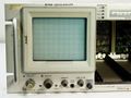
7704-front.jpg | 7704 front | |||
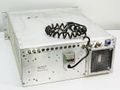
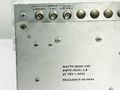
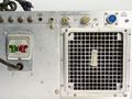
Tek_7704_rear.jpg | 7704 rear | |||
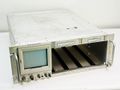
Tek 7704 2.jpg | 7704 CRT and controls | |||
Tek_7704_left.jpg | Left internal | |||
Tek 7704 right.jpg | Right internal | |||
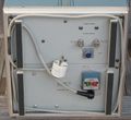
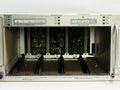
7704_powersupply.jpg | Left side of 7704 contains power supply | |||
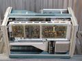
7704 right2.jpg | Right side of 7704 contains readout circuitry | |||
Tek_7704_trace_photo.png | A 7704 displaying the output of a function generator. | |||
</gallery> | |||
===R7704=== | |||
<gallery> | <gallery> | ||
R7704_front_diag.jpg |R7704 front | |||
R7704_front_left.jpg |R7704 front left (Screen) | |||
R7704_front_right.jpg|R7704 front right (plugin bay) | |||
R7704_rear.jpg |R7704 rear | |||
R7704_rear_left.jpg |R7704 rear left | |||
R7704_rear_right.jpg |R7704 rear right | |||
</gallery> | </gallery> | ||
==Components== | |||
{{Parts|7704}} | |||
{{Custom ICs|7000 series readout system}} | |||
[[Category:7000 series non-storage mainframes]] | [[Category:7000 series non-storage mainframes]] | ||
Latest revision as of 03:50, 3 March 2024

The Tektronix 7704 is a 150 MHz, four-bay mainframe, one of the initial oscilloscopes introducing the 7000-Line in August 1969.
It is very lavishly built, using contacts embedded in the aluminium frame for interconnecting the gold plated circuit boards. It also features the 7000-series remote control connector on the rear panel.
It can take two 7000-series vertical plug-ins and two 7000-series horizontal plug-ins.
It was superseded by the completely redesigned 7704A in 1973. There is also a rack-mount version, the R7704, that was produced until 1985, still with the original specifications (150 MHz) of the 7704.
Key Specifications
| Bandwidth | 150 MHz (with 7A11 or 7A16) |
|---|---|
| Fastest calibrated sweep | 2 ns/Div |
| Calibrator | DC, square wave (1 kHz or 1/2 B Sweep gate), 4 mV to 40 V in decade steps (2/20/200/400 mV into 50 Ω); 40 mA current loop |
| Vertical modes | Left / Alt / Add / Chop / Right |
| Horizontal modes | A / Alt / Chop / B |
| Trigger Source | Left / Vert Mode / Right |
| Inputs |
|
| Outputs |
|
| CRT | 8x10 Div @ 1cm/Div internal gradicule, 154-0609-00 distributed vertical deflection plates, with P31 phosphor, 24 kV acceleration (+21/-2.96) |
| Options |
|
| Power | 90−136 V or 180−272 V, 48−440 Hz, 210 W max. |
| Weight | 19.1 kg (42 lbs) |
| Size |
|
Operation
The 7704 has several modes of operation, all outlined in the manual:
- Single-Trace Display
- Vertical Mode: Left, Horizontal Mode: A. Single-trace vertical plugin installed in the left vertical compartment, single-timebase plugin installed in horizontal compartment A.
- Provides a display of a single-trace vertical unit against one time-base unit.
- Note: Any combination of one vertical and one horizontal plugin can be chosen as needed.
- Dual-Trace Display
- Vertical Mode: Alt or Chop, Horizontal Mode: A. Single-trace vertical plugins installed in both vertical compartments, single-timebase plugin installed in horizontal compartment A.
- Provides a display of two single-trace vertical units against one time-base unit.
- Dual-Sweep Display
- Vertical Mode: Left, Horizontal Mode: Alt or Chop. Single-trace vertical plugin installed in the left vertical compartment, single-timebase plugins installed in both horizontal compartments.
- Provides a dual-sweep display of a single-trace vertical unit against two time-base units.
- Dual-Trace/Dual-Sweep Display
- Vertical Mode: Chop, Horizontal Mode: Alt or Chop. Single-trace vertical plugins installed in both vertical compartments, single-timebase plugins installed in both horizontal compartments.
- Provides a dual-trace, dual-sweep display of two single-trace vertical units against two time-base units (four total traces)
- Sweep-Slaving Display
- Vertical Mode: Alt, Horizontal Mode: Alt or Chop. Single-trace vertical plugins installed in both vertical compartments, single-timebase plugins installed in both horizontal compartments.
- Provides a dual-trace, dual-sweep display where the left vertical plugin is displayed at the sweep rate of the B timebase plugin, and similarly for the right vertical and A horizontal plugins.
- Delayed-Sweep Display
- Vertical Mode: Left, Horizontal Mode: Alt or Chop. Single-trace vertical plugin installed in the left vertical compartment. Delaying timebase plugin installed in horizontal compartment A, and a single-timebase plugin installed in horizontal-compartment B.
- Provides a simultaneous display of a delaying timebase and delayed timebase, providing an effective "zoom" function.
- X-Y Display
- Vertical Mode: Left, Horizontal Mode: A. Single-trace vertical plugins installed in both the left vertical compartment and the A horizontal compartment.
- The X signal is input into the A horizontal plugin while the Y signal is input into the left vertical plugin. Alternatively, some 7B series timebase plugins include X-Y capability.
Due to the modular design of the instrument, there are many more possible modes of operation. For example, horizontal plugins can be installed in both the vertical and horizontal plugins to provide a raster display, or dual-trace plugins can be used in any of the above configurations.
Internals
The 7704 was the first Tek lab scope to employ a switch-mode power supply (SMPS)[1]. The SMPS, designed by Gene Andrews, uses an all-discrete resonant half-bridge topology. The CRT voltages and heating are produced in a separate switching stage running off the main SMPS DC output.
Logic, channel switching, and readout use the classic TEK 7000 series custom ICs (155-0009-00 to 155-0022-00), the vertical amplifier (also designed by Andrews) and the horizontal amplifier are completely discrete.
The 7704 does not implement the Aux Y input (B16), therefore the Trace Separation control on a 7B92/7B92A will have no effect. (This was implemented on the 7704's successor, the 7704A.)
The 7704 contains a mercury-based elapsed time meter on the low voltage regulator board.
Links
Documents Referencing 7704
| Document | Class | Title | Authors | Year | Links |
|---|---|---|---|---|---|
| Tekscope 1969 V1 N5 Oct 1969.pdf | Article | Introducing the New Generation | 1969 | 7000-series scopes • 7504 • 7704 • 7A11 • 7A12 • 7A13 • 7A14 • 7A16 • 7A22 • 7S11 • 7M11 • 7B50 • 7B51 • 7B70 • 7B71 • 7T11 • R5030 • 7000 series readout system • Miniature relays • Cam switches • Industrial Design • T7500 • T7700 • P6052 • P6053 • C-50 • C-51 • 204-2 | |
| Tekscope 1969 V1 N6 Dec 1969.pdf | Article | A New Logic for Oscilloscope Displays | 1969 | 7000-series scopes • 7A11 • 7A12 • 7A13 • 7A14 • 7A16 • 7A22 • 7B50 • 7B51 • 7B70 • 7B71 • 7S11 • 7T11 • 7504 • 7704 | |
| Tekscope 1970 V2 N3 Jun 1970.pdf | Article | The 7000-Series Oscilloscopes as Signal Sources | 1970 | 7704 • 7504 • 7503 | |
| Tekscope 1971 V3 N2.pdf | Article | Servicing the 7704 High-Efficiency Power Supply | Charles Phillips | 1971 | 7704 |
| Tekscope 1971 V3 N3 May 1971.pdf | Article | Servicing the 7704 CRT Circuit | Charles Phillips | 1971 | 7704 |
References
- ↑ See Tekscope Vol.4 No.2, March 1972, p.5
Pictures
-

7704 front
-
7704 rear
-
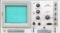
7704 CRT and controls
-
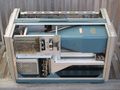
Left internal
-
Right internal
-

Left side of 7704 contains power supply
-

Right side of 7704 contains readout circuitry
-
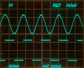
A 7704 displaying the output of a function generator.


R7704
-
R7704 front
-
R7704 front left (Screen)
-
R7704 front right (plugin bay)
-
R7704 rear
-
R7704 rear left
-
R7704 rear right


Components
Some Parts Used in the 7704
| Part | Part Number(s) | Class | Description | Used in |
|---|---|---|---|---|
| 155-0009-00 | 155-0009-00 | Monolithic integrated circuit | horizontal lockout logic | 7504 • 7514 • 7704 • 7704A • R7704 • 7834 • 7844 • 7854 • 7904 • R7903 • 7904A • 7934 • 7104 |
| 155-0010-00 | 155-0010-00 | Monolithic integrated circuit | chop divider and blanking | 7504 • 7514 • 7704 • R7704 • 7704A • 7834 • 7854 • 7904 • R7903 • 7904A • 7934 • 7104 |
| 155-0011-00 | 155-0011-00 | Monolithic integrated circuit | clock and chop blanking | 485 • 7313 • 7403N • R7403N • 7503 • 7504 • 7514 • 7603 • AN/USM-281C • 7613 • 7623 • 7623A • 7633 • 7704 • R7704 • 7704A • 7834 • 7844 • 7854 • 7904 • 7904A • R7903 • R7912 • 7912AD • 7912HB • 7934 • 7104 • R7103 • AN/USM-281C |
| 155-0012-00 | 155-0012-00 | Monolithic integrated circuit | Z Axis Logic | 485 • 7504 • 7514 • 7704 • R7704 • 7704A • 7834 • 7844 • 7854 • 7904 • R7903 • 7904A • R7912 • 7934 • 7912AD • 7912HB • 7104 • R7103 |
| 155-0013-00 | 155-0013-00 • 155-0013-01 | Monolithic integrated circuit | horizontal chop and alt. binary | 7504 • 7514 • 7704 • R7704 • 7704A • 7834 • 7854 • 7904 • 7904A • R7903 • 7934 • 7104 |
| 155-0022-00 | 155-0022-00 • 155-0022-01 | Monolithic integrated circuit | analog multiplexer | 147 • 148 • 149 • 335 • 468 • 1430 • 1441 • 1461 • 1900 • 1910 • 2220 • 2221 • 2230 • 5223 • 5403 • 5440 • 5441 • 5443 • 5444 • 5A38 • 7313 • 7403N • 7503 • 7504 • 7514 • 7603 • AN/USM-281C • 7613 • 7623 • 7623A • 7633 • 7704 • R7704 • 7704A • 7834 • 7844 • 7854 • R7912 • 7912AD • 7912HB • 7904 • R7903 • 7904A • 7934 • 7A12 • 7A18 • 7A18A • 7A18N • 7B52 • 7B53N • 7D10 • 7D11 • 7D12 • NT-7000 • P7001 |
| T7700 | 154-0609-00 | CRT | CRT | 7704 |