7D12: Difference between revisions
No edit summary |
No edit summary |
||
| (12 intermediate revisions by 2 users not shown) | |||
| Line 1: | Line 1: | ||
{{Plugin Sidebar | {{Plugin Sidebar | ||
manufacturer=Tektronix | type=7D12 | | |manufacturer=Tektronix | ||
summary= | |series=7000-series scopes | ||
image=7d12- | |type=7D12 | ||
caption=7D12 with M2 Sample and Hold Module | |summary=digital meter plugin | ||
|image=7d12-m2-front.jpg | |||
introduced=1974 | | |caption=7D12 with M2 Sample and Hold Module | ||
discontinued=1986 | | |introduced=1974 | ||
manuals= | |discontinued=1986 | ||
* [[Media:070-1470-00.pdf|Tektronix 7D12 Service]] (OCR | |manuals= | ||
* [[Media:070-1469-00.pdf| M1-M2-M3 Operators Manual | * [[Media:070-1470-00.pdf|Tektronix 7D12 Service]] (OCR) | ||
* [[Media:7D12-M2.pdf | M2 Sample/Hold | * [[Media:070-1469-00.pdf| M1-M2-M3 Operators Manual]] | ||
* [[Media:070-1513-00.pdf | M3 RMS Module | * [[Media:Tek m1 interim.pdf |Tektronix M1 Interim Manual]] | ||
* [[Media:7000 Series Digital Plug-In Applications.pdf|7000 Series Digital Plug-In Applications | * [[Media:7D12-M2.pdf | M2 Sample/Hold]] | ||
* [[Media:070-1513-00.pdf | M3 RMS Module]] | |||
* [[Media:7000 Series Digital Plug-In Applications.pdf|7000 Series Digital Plug-In Applications]] | |||
}} | }} | ||
The '''Tektronix 7D12''' is an A/D converter (digital meter) plug-in for [[7000-series scopes]]. The A/D converter can be triggered internally (when installed in a horizontal bay), manually by a front panel switch, or externally from a trigger source. The 7D12 will trigger automatically at approximately 4 Hz if set to Auto. It contains a vertical display amplifier that displays the signal being applied to the module and a gate display amplifier that displays a representation of the 7D12 internal gate signal. | The '''Tektronix 7D12''' is an A/D converter (digital meter) plug-in for [[7000-series scopes]]. The A/D converter can be triggered internally (when installed in a horizontal bay), manually by a front panel switch, or externally from a trigger source. The 7D12 will trigger automatically at approximately 4 Hz if set to Auto. It contains a vertical display amplifier that displays the signal being applied to the module and a gate display amplifier that displays a representation of the 7D12 internal gate signal. | ||
| Line 20: | Line 22: | ||
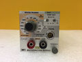
* M1 is a digital multimeter module with DC voltage, resistance and temperature (with [[P6058]]) ranges. It does not produce an analog output signal. | * M1 is a digital multimeter module with DC voltage, resistance and temperature (with [[P6058]]) ranges. It does not produce an analog output signal. | ||
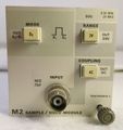
* M2 is a sample and hold module that can measure voltage from ground to a selected point, or the difference voltage between two points defined by a trigger signal. When triggered by the delayed gate signal from a time base, this allows cursor-like measurements to be made. The module has an aperture time of only 10 ns. With repetitive signals, the period between the sampled points can be as short as 30 ns, in single shot mode it must be at least 150 μs. <br />Input sensitivity is selectable between ±2 V (100/200/500 mV/Div) and ±20 V (1/2/5 V/Div) ranges. The input has a ring to detect a ×10 probe with [[readout pin]] ([[P6055]] recommended) and adjusts the display accordingly. Signal bandwidth is 25 MHz. | * M2 is a sample and hold module that can measure voltage from ground to a selected point, or the difference voltage between two points defined by a trigger signal. When triggered by the delayed gate signal from a time base, this allows cursor-like measurements to be made. The module has an aperture time of only 10 ns. With repetitive signals, the period between the sampled points can be as short as 30 ns, in single shot mode it must be at least 150 μs. <br />Input sensitivity is selectable between ±2 V (100/200/500 mV/Div) and ±20 V (1/2/5 V/Div) ranges. The input has a ring to detect a ×10 probe with [[readout pin]] ([[P6055]] recommended) and adjusts the display accordingly. Signal bandwidth is 25 MHz. | ||
* M3 is a True RMS module with floating inputs. It produces an analog output signal with a 3 dB bandwidth of 700 kHz and vertical sensitivities between 100 mV/Div | * M3 is a True RMS module with floating inputs. It produces an analog output signal with a 3 dB bandwidth of 700 kHz and vertical sensitivities between 100 mV/Div to 500 V/Div in a 1−2−5 sequence. The RMS converter is implemented with opamps, a dual transistor, and transistors from a [[CA3046]] array. | ||
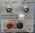
* [[067-0700-00]] is a calibration fixture. | * [[067-0700-00]] is a calibration fixture. | ||
==Links== | ==Links== | ||
{{Documents|Link=7D12}} | |||
==Pictures== | ==Pictures== | ||
<gallery> | <gallery> | ||
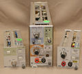
7d12-m2-front.jpg | 7D12 with M2 Sample and Hold Module | |||
Tek 7d12 with m1 m2 m3.jpg | 7D12 with M1, M2 and M3 | Tek 7d12 with m1 m2 m3.jpg | 7D12 with M1, M2 and M3 | ||
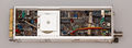
7d12-empty-left.jpg | 7D12 without plug-in, left side | 7d12-empty-left.jpg | 7D12 without plug-in, left side | ||
| Line 51: | Line 53: | ||
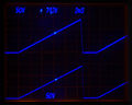
M2 display 1.jpg | 7D12/M2 displaying sawtooth from [[585]] (lower trace), triggered with delayed gate output from a [[7B53A]] (intensified). | M2 display 1.jpg | 7D12/M2 displaying sawtooth from [[585]] (lower trace), triggered with delayed gate output from a [[7B53A]] (intensified). | ||
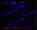
M2 display 2.jpg | | M2 display 2.jpg | | ||
Master sampler cartoon.png | "Master Sampler" cartoon in schematic | Master sampler cartoon.png | "Master Sampler" [[cartoon]] in schematic | ||
</gallery> | </gallery> | ||
| Line 58: | Line 60: | ||
Tek m3 1.jpg | M3 plug-in, front | Tek m3 1.jpg | M3 plug-in, front | ||
Tek m3 2.jpg | M3 plug-in, rear | Tek m3 2.jpg | M3 plug-in, rear | ||
7D12-M3 Least Significant Digit Blanking cartoon.png | "Least Significant Digit Blanking" [[cartoon]] in schematic | |||
</gallery> | </gallery> | ||
==Components== | |||
{{Parts|7D12}} | |||
[[Category:7000 series special-function plugins]] | [[Category:7000 series special-function plugins]] | ||
Latest revision as of 02:38, 26 February 2024
The Tektronix 7D12 is an A/D converter (digital meter) plug-in for 7000-series scopes. The A/D converter can be triggered internally (when installed in a horizontal bay), manually by a front panel switch, or externally from a trigger source. The 7D12 will trigger automatically at approximately 4 Hz if set to Auto. It contains a vertical display amplifier that displays the signal being applied to the module and a gate display amplifier that displays a representation of the 7D12 internal gate signal.

The 7D12 accepts plug-in modules M1, M2, or M3.
- M1 is a digital multimeter module with DC voltage, resistance and temperature (with P6058) ranges. It does not produce an analog output signal.
- M2 is a sample and hold module that can measure voltage from ground to a selected point, or the difference voltage between two points defined by a trigger signal. When triggered by the delayed gate signal from a time base, this allows cursor-like measurements to be made. The module has an aperture time of only 10 ns. With repetitive signals, the period between the sampled points can be as short as 30 ns, in single shot mode it must be at least 150 μs.
Input sensitivity is selectable between ±2 V (100/200/500 mV/Div) and ±20 V (1/2/5 V/Div) ranges. The input has a ring to detect a ×10 probe with readout pin (P6055 recommended) and adjusts the display accordingly. Signal bandwidth is 25 MHz. - M3 is a True RMS module with floating inputs. It produces an analog output signal with a 3 dB bandwidth of 700 kHz and vertical sensitivities between 100 mV/Div to 500 V/Div in a 1−2−5 sequence. The RMS converter is implemented with opamps, a dual transistor, and transistors from a CA3046 array.
- 067-0700-00 is a calibration fixture.
Links
Documents Referencing 7D12
| Document | Class | Title | Authors | Year | Links |
|---|---|---|---|---|---|
| Tekscope 1973 V5 N6 Nov 1973.pdf | Article | A fast A/D plug-in for the oscilloscope | Hideki Iwata • Ken Sternes | 1973 | 7D12 • M1 • M2 • M3 |
| Tekscope 1975 V7 N5.pdf | Article | Delayed Gate Aids Oscilloscope Digital Measurements | Dave McCullough | 1975 | 7D12 • 7D14 • 7D15 • 7B53A |
| 7000 Series Digital Plug-In Applications.pdf | Application Note | 7000 Series Digital Plug-In Applications | 1977 | 7D10 • 7D11 • 7D12 • 7D13 • 7D14 • 7D15 |
Pictures
-

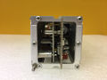
7D12 with M2 Sample and Hold Module
-
7D12 with M1, M2 and M3
-
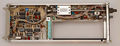
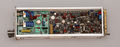
7D12 without plug-in, left side
-
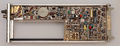
7D12 without plug-in, right side
-

7D12 with M2 plug-in, left side
-
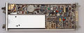
7D12 with M2 plug-in, right side
-
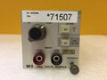
067-0700-00 calibration plug-in


M1
-
M1 plug-in, front
-

M1 plug-in, rear


M2
-
M2 front
-
M2 plug-in, left side
-
M2 plug-in, right side
-
-
-

"Master Sampler" cartoon in schematic


M3
-
M3 plug-in, front
-
M3 plug-in, rear
-
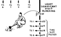
"Least Significant Digit Blanking" cartoon in schematic


Components
Some Parts Used in the 7D12
| Part | Part Number(s) | Class | Description | Used in |
|---|---|---|---|---|
| 155-0022-00 | 155-0022-00 • 155-0022-01 | Monolithic integrated circuit | analog multiplexer | 147 • 148 • 149 • 335 • 468 • 1430 • 1441 • 1461 • 1900 • 1910 • 2220 • 2221 • 2230 • 5223 • 5403 • 5440 • 5441 • 5443 • 5444 • 5A38 • 7313 • 7403N • 7503 • 7504 • 7514 • 7603 • AN/USM-281C • 7613 • 7623 • 7623A • 7633 • 7704 • R7704 • 7704A • 7834 • 7844 • 7854 • R7912 • 7912AD • 7912HB • 7904 • R7903 • 7904A • 7934 • 7A12 • 7A18 • 7A18A • 7A18N • 7B52 • 7B53N • 7D10 • 7D11 • 7D12 • NT-7000 • P7001 |
| 155-0090-00 | 155-0090-00 • 155-0090-01 • 155-0090-02 | Monolithic integrated circuit | four-decade counter, latch and D/A converter | 7B85 • 7D01 • 7D12 • 7D15 • 7J20 |
| 155-0171-00 | 155-0171-00 | Monolithic integrated circuit | four-decade counter, latch and D/A converter | 7B85 • 7D01 • 7D12 • 7D15 • 7J20 |
| CA3046 | 156-0048-00 | Monolithic integrated circuit | transistor array | 7104 • 7403N • 7503 • 7B53A • 7D12 • DM502 • FG504 • S-52 • Telequipment D34 • 7603 • 7613 • 7623 • 7633 |