519: Difference between revisions
(on limited demand list in 1973 catalog) |
No edit summary |
||
| (30 intermediate revisions by 4 users not shown) | |||
| Line 1: | Line 1: | ||
{{Oscilloscope Sidebar | | {{Oscilloscope Sidebar | ||
|manufacturer=Tektronix | |||
summary=1 GHz tube scope | | |series= | ||
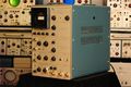
image=Tek 519 | |designers=Cliff Moulton | ||
caption=Tek 519 | | |model= 519 | ||
introduced=1961 | | |summary=1 GHz tube scope | ||
discontinued=1974 | | |image=Tek 519 with bezel.jpg | ||
manuals= | |caption=Tek 519 | ||
* [ | |introduced=1961 | ||
|discontinued=1974 | |||
|manuals= | |||
* [[Media:070-243.pdf|Tek 519 manual]] (OCR, color, whole schematics) | |||
* [[Media:Tek 519 with mods.pdf|Tek 519 manual with Modifications]] (split schematics, OCR) | |||
* [[Media:Tek 519 early.pdf|Tektronix 519 Early Manual]] (OCR) | |||
}} | }} | ||
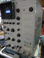
The '''Tektronix 519''' is a high-speed oscilloscope made by Tektronix from | The '''Tektronix 519''' is a high-speed oscilloscope made by Tektronix from | ||
[[introduced_in_1961|1961]] | [[introduced_in_1961|1961]] until 1974. | ||
It was designed by [[Cliff Moulton]], who also designed the Type [[130]] LC Meter. | It was designed by [[Cliff Moulton]], who also designed the Type [[130]] LC Meter. | ||
== No Vertical Amplifier == | {{BeginSpecs}} | ||
{{Spec | Channels | One vertical channel }} | |||
{{Spec | Bandwidth | DC to 1 GHz }} | |||
{{Spec | Rise time | < 0.35 ns }} | |||
{{Spec | Deflection | < 10 V/div, CRTs individually calibrated }} | |||
{{Spec | Sweep | 2 ns/div to 1 μs/div }} | |||
{{Spec | CRT | [[154-356]], [[154-308]] for serial numbers ≥1017 }} | |||
{{Spec | Input impedance | 125 Ω }} | |||
{{Spec | Power consumption | 650 W }} | |||
{{EndSpecs}} | |||
==Internals== | |||
=== No Vertical Amplifier === | |||
The 519 is very unusual in that it does not contain vertical amplifiers. | The 519 is very unusual in that it does not contain vertical amplifiers. | ||
The input signal is passively connected to the | The input signal is passively connected to the [[distributed vertical deflection plates]] of the CRT, | ||
[[distributed vertical deflection plates]] of the CRT, | |||
which are driven single-ended. | which are driven single-ended. | ||
This allows the scope to have 1 GHz bandwidth. | This allows the scope to have 1 GHz bandwidth. | ||
The vertical deflection factor is approximately 10 V/cm. | The vertical deflection factor is approximately 10 V/cm. | ||
== CRT == | === CRT === | ||
The viewing area is two centimeters vertical, six centimeters | The viewing area is two centimeters vertical, six centimeters horizontal. | ||
horizontal. | The spot diameter on the CRT is 0.1 mm, | ||
which corresponds to 100 mV at the input connector. | which corresponds to 100 mV at the input connector. | ||
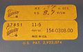
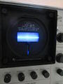
Each CRT was individually characterized for risetime and | Each CRT was individually characterized for risetime and deflection sensitivity and the precise value was written | ||
deflection sensitivity and the precise value was written | on the CRT and on the CRT bezel. For serial numbers 1016 and below, the CRT part number is [[154-356]]. | ||
on the CRT and on the CRT bezel. For serial numbers 1016 and below, | For serial numbers 1017 and up, the CRT part number is [[154-308]]. | ||
the CRT part number is [[154-356]]. For serial numbers 1017 and up, the | |||
CRT part number is [[154-308]]. | |||
== 125 Ω Input Impedance == | === 125 Ω Input Impedance === | ||
The input to the 519 has an impedance of 125 Ω. | The input to the 519 has an impedance of 125 Ω. | ||
The input connector is a special | The input connector is a special 125 Ω [[GR-874 connector]] made by Tektronix | ||
that is neither electrically nor mechanically compatible with the much more | that is neither electrically nor mechanically compatible with the much more | ||
common 50 Ω GR-874 connector. Tek made a resistive impedance matching | common 50 Ω GR-874 connector. Tek made a resistive impedance matching | ||
adapter, the [[017-053]], which presents a 50 Ω input (but attenuates the signal). | adapter, the [[017-053]], which presents a 50 Ω input (but attenuates the signal). | ||
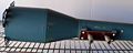
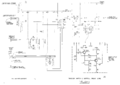
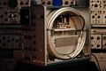
== Rigid Coax Delay Line == | === Rigid Coax Delay Line === | ||
To allow viewing of the leading edge of pulses, there is a | To allow viewing of the leading edge of pulses, there is a rigid coaxial 45 ns [[delay line]] between the input and the CRT. | ||
rigid coaxial 45 ns [[delay line]] between the input and the CRT. | |||
[[File:519delay.jpg|thumb]] | [[File:519delay.jpg|thumb]] | ||
Note that 45 nanoseconds is an unusually short delay. | Note that 45 nanoseconds is an unusually short delay. | ||
For comparison, the delay line in a [[547]] is 170 ns. | For comparison, the delay line in a [[547]] is 170 ns. | ||
Keeping the delay short minimizes degradation of fast pulses, | Keeping the delay short minimizes degradation of fast pulses, | ||
but it necessitates a trigger and sweep circuit with quick response. | but it necessitates a trigger and sweep circuit with quick response. | ||
A 519 can also be used with a pretrigger pulse generator like the [[111]]. | A 519 can also be used with a pretrigger pulse generator like the [[111]]. | ||
== Trigger and Sweep == | === Trigger and Sweep === | ||
The sweep is triggered using a 20 mA, 4 pF [[tunnel diodes|tunnel diode]]. | The sweep is triggered using a 20 mA, 4 pF [[tunnel diodes|tunnel diode]]. | ||
The horizontal deflection ramp signal of a 519 is generated | The horizontal deflection ramp signal of a 519 is generated by a [[4CX250F]] external anode, | ||
by a [[4CX250F]] external anode, radial-beam tube that is cooled | radial-beam tube that is cooled by forced air sent from a blower through a duct. | ||
by forced air sent from a blower through a duct. | |||
The total accelerating voltage of the 519 is 24 kV. | The total accelerating voltage of the 519 is 24 kV. | ||
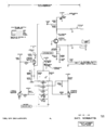
The 519 contains a calibration step generator that produces voltage steps with 100 picosecond | The 519 contains a calibration step generator that produces voltage steps with 100 picosecond rise time, | ||
rise time, and a rate generator that generates pulses with 500 ps rise times. The step generator | and a rate generator that generates pulses with 500 ps rise times. | ||
utilizes a charged line which is discharged through a reed relay, while the rate generator uses | The step generator utilizes a charged line which is discharged through a reed relay, | ||
a transistor in avalanche configuration. | while the rate generator uses a transistor in avalanche configuration. | ||
by listening to it. | The reed relay in the step generator is tuned in part by listening to it. | ||
== Unusual Physical Construction == | == Unusual Physical Construction == | ||
The physical construction and styling of the 519 differs from that of the other Tek scopes of | The physical construction and styling of the 519 differs from that of the other Tek scopes of the same period. | ||
the same period. | There are multiple reasons for this. | ||
First, it has an unusually long CRT. | |||
Also, the large 125 Ω coaxial delay line (seen in the photo) had to fit inside the cabinet. | Also, the large 125 Ω coaxial delay line (seen in the photo) had to fit inside the cabinet. | ||
| Line 71: | Line 84: | ||
The mass of these extra components necessitated a larger, sturdier cabinet than, for example, the [[545]]. | The mass of these extra components necessitated a larger, sturdier cabinet than, for example, the [[545]]. | ||
The sheet aluminum used in the case of the 519 is thicker than that of the other Tek scopes of the period. | The sheet aluminum used in the case of the 519 is thicker than that of the other Tek scopes of the period. | ||
The 519 weighs 99 pounds and | The 519 weighs 99 pounds and consumes 650 watts. | ||
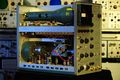
== Different CRT Bezels == | == Different CRT Bezels == | ||
The 519 came with two different bezels. | The 519 came with two different bezels. | ||
Pictured in Tek Catalog 20 through 26 is the early version which was actually a camera mount designed to | Pictured in Tek Catalog 20 through 26 is the early version which was actually a camera mount designed to | ||
be compatible with the C19 camera. | be compatible with the [[C19|C19 camera]]. | ||
It had a unique removable part with a graticule that could be slid down | |||
such that it would not be in between the CRT beam and the camera lens. | such that it would not be in between the CRT beam and the camera lens. | ||
Most of the non-used area of the CRT faceplate was covered by the black plastic material of the graticule cover. | Most of the non-used area of the CRT faceplate was covered by the black plastic material of the graticule cover. | ||
This graticule cover was changed slightly as is shown in the pictures of the 519 in Tek Catalogs 27 and later. | This graticule cover was changed slightly as is shown in the pictures of the 519 in Tek Catalogs 27 and later. | ||
It still was designed to mount the C19 camera. | It still was designed to mount the C19 camera. | ||
''(For what reason was the bezel design changed?)'' | |||
The 519 is probably the only Tek scope to come standard with a camera mount for a bezel. You had to buy camera | The 519 is probably the only Tek scope to come standard with a camera mount for a bezel. | ||
mounting frames as accessories for the other scopes. | You had to buy camera mounting frames as accessories for the other scopes. | ||
== Production == | == Production == | ||
Early 519's in the '61-'66 period were calibrated in Plant 2 in a group managed | Early 519's in the '61-'66 period were calibrated in Plant 2 in a group managed by Bob Randall. | ||
by Bob Randall. | Three of the men calibrating 519's in that period were [[Stan Griffiths]], [[Dick Bellamy]], | ||
[[Stan Griffiths]], [[Dick Bellamy]], and John A. (What is John's last name?) | and John A. (What is John's last name?) | ||
During this period, Cliff Moulton would visit the calibration operation to answer | During this period, Cliff Moulton would visit the calibration operation to answer | ||
any questions that would arise as the scopes were being prepared for shipment | any questions that would arise as the scopes were being prepared for shipment | ||
to customers. | to customers. | ||
Later 519's were calibrated at Plant 2 Test-Final in a group managed by Jack | Later 519's were calibrated at Plant 2 Test-Final in a group managed by Jack Lyngdal. | ||
Lyngdal. | Two of the calibration people that worked there were Norm Jenkins and Jack. | ||
and Jack. | (What is Jack's last name?) | ||
later period was Mark Balcom. | Another man who calibrated 519's in this later period was Mark Balcom. | ||
The distributed deflection plate delay network had to be hand-trimmed, which was done | The distributed deflection plate delay network had to be hand-trimmed, | ||
to putting it inside the CRT envelope. | which was done prior to putting it inside the CRT envelope. | ||
It is possible that this was done using a TDR. | |||
== 519C: A 3 GHz Version of the 519 == | == 519C: A 3 GHz Version of the 519 == | ||
Tektronix Catalog 22 (mid'63-mid'64) refers to a modified 519 with response extended to 3 GHz : | Tektronix Catalog 22 (mid'63-mid'64) refers to a modified (MOD 795) 519 with response extended to 3 GHz: | ||
<blockquote> | <blockquote> | ||
DC-to-3 GIGACYCLE OSCILLOSCOPE: | DC-to-3 GIGACYCLE OSCILLOSCOPE: | ||
This modified Type 519 Oscilloscope incorporates a coaxial-deflection crt to | This modified Type 519 Oscilloscope incorporates a coaxial-deflection crt | ||
achieve a risetime of 0.13nsec, corresponding to a 3000-Mc bandwidth. Deflection | to achieve a risetime of 0.13nsec, corresponding to a 3000-Mc bandwidth. | ||
factor is approximately 180v/cm. Usable viewing area is 2x4 cm. Consult your FE | Deflection factor is approximately 180v/cm. | ||
to learn about the advantages, limitations, and delivery time on this or other | Usable viewing area is 2x4 cm. | ||
modified instruments." | Consult your FE to learn about the advantages, limitations, and delivery time on this or other modified instruments." | ||
</blockquote> | </blockquote> | ||
A [[Media:Campbell83 transient recorders.pdf|1983 IEEE Transactions on Nuclear Science paper]] | |||
The 519C | includes a chart that mentions in Figure 10 the 3 GHz 519C [[introduced in 1963]]. | ||
The 519C was sold to Lawrence Livermore Labs and the Nuclear Test Site. | |||
The 519C uses the [[T5192]] CRT. | |||
* [http://bama.edebris.com/download/tek/519/519.djvu 519 manual] (DJVU) | * [http://bama.edebris.com/download/tek/519/519.djvu 519 manual] (DJVU) | ||
* [http://w140.com/tek_519_1968_catalog.pdf Tektronix 519 in 1968 Catalog (PDF) | * [http://w140.com/tek_519_1968_catalog.pdf Tektronix 519 in 1968 Catalog] (PDF) | ||
The 519 came with a set of adapters performing various functions such as interfacing the | |||
125 Ω input impedance of the 519 with the more common 50 Ω impedance of many cables and instruments. | |||
One example is the [[017-0019-00]]. | |||
==See Also== | |||
* [[017-053]] | |||
==Pictures== | |||
<gallery> | <gallery> | ||
<!--Tek 519 front.jpg|519 front view--> | |||
519_adaptkit.jpg|519 adapter kit | |||
519_adaptkit2.jpg|519 adapter kit case | |||
519 left.JPG | |||
519 right.JPG|Delay line around the EHT section | |||
Spiroline cross-section.jpg | Cross section of Spir-o-line rigid coax (delay line) | |||
519 crt defl.jpg|CRT deflection trimmers* | |||
519_defl_drawing.gif|Drawing from Devere book | |||
519 blower.JPG|Blower and duct | |||
519 sweeptube.JPG|Sweep tube and duct | |||
519 vert term2.JPG|Vertical terminator | |||
519 triggerpickoff.JPG|Trigger pickoff | |||
519 left rear.JPG | |||
519 sweepswitch.JPG | |||
519 board2.JPG | |||
519 board1.JPG | |||
519 hv psu.JPG | high voltage power supply | |||
519 crt in shield.jpg | |||
519 crt in shield2.jpg | |||
519 crt label.jpg | |||
Tek-519 rate gen.png|Rate Generator (early) | |||
Tek-519 rate gen late.png|Rate Generator (late) | |||
Tek-519 power supply.png|Power Supply | |||
Tek-519 heater supply and wiring.png|Heater Supply and Wiring | |||
Tek-519 timebase gen.png|Timebase Generator | |||
Tek-519 timing switch.png|Timing Switch | |||
Tek-519 timebase gate and unblanking.png|Timebase Gate and Unblanking | |||
Tek-519 crt circuit.png|CRT Circuit | |||
Tek-519 timebase trig and holdoff.png|Timebase Trigger and Holdoff | |||
Tek-519 cal step gen.png|Calibration Step Generator | |||
Tek-519 trig sw and vert delay.png|Trigger Switch and Vertical Delay | |||
Timkoeth 519 TWK 6541.jpg | |||
Timkoeth 519 TWK 6537.jpg | |||
Timkoeth 519 TWK 6529.jpg | |||
Timkoeth 519 TWK 6509.jpg | |||
Timkoeth 519 TWK 6448.jpg | |||
Timkoeth 519 TIM 4443.jpg|Homebrew Mount for DSLR | |||
Timkoeth 519 TWK 1379.jpg|800 ps (FWHM) pulse from [[109|Tek 109 pulse generator]], repetitive, 2 ns/div. | |||
Timkoeth 519 TWK 6627.jpg|800 ps (FWHM) pulse from [[109|Tek 109 pulse generator]], 2 ns/div single shot taken with Nikon D3s | |||
Tek 519 left hires.jpg | |||
Tek 519 tx1.jpg | |||
Tek 519 tx2.jpg | |||
Tek 519 tx3.jpg | |||
Tek 519C in feb 1 1963 tekweek.jpg|February 1, 1963 Tekweek referencing the T519C | |||
</gallery> | </gallery> | ||
* CRT photo courtesy of [http://www.collection.archivist.info collection.archivist.info] | * CRT photo courtesy of [http://www.collection.archivist.info collection.archivist.info] | ||
* See Oscilloscope Cathode-Ray Tubes by Chuck Devere, page 30-35 | * See [[Media:062-0852-01.pdf | Oscilloscope Cathode-Ray Tubes by Chuck Devere]], page 30-35. | ||
* See [http://www.timkoeth.com/?cat=5 Tim Koeth's Page on the Tektronix 519] | * See [http://www.timkoeth.com/?cat=5 Tim Koeth's Page on the Tektronix 519] | ||
==Components== | |||
{{Parts|519}} | |||
[[Category:Monolithic tube scopes]] | [[Category:Monolithic tube scopes]] | ||
Latest revision as of 10:51, 9 December 2023

The Tektronix 519 is a high-speed oscilloscope made by Tektronix from 1961 until 1974. It was designed by Cliff Moulton, who also designed the Type 130 LC Meter.
Key Specifications
| Channels | One vertical channel |
|---|---|
| Bandwidth | DC to 1 GHz |
| Rise time | < 0.35 ns |
| Deflection | < 10 V/div, CRTs individually calibrated |
| Sweep | 2 ns/div to 1 μs/div |
| CRT | 154-356, 154-308 for serial numbers ≥1017 |
| Input impedance | 125 Ω |
| Power consumption | 650 W |
Internals
No Vertical Amplifier
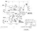
The 519 is very unusual in that it does not contain vertical amplifiers. The input signal is passively connected to the distributed vertical deflection plates of the CRT, which are driven single-ended. This allows the scope to have 1 GHz bandwidth. The vertical deflection factor is approximately 10 V/cm.
CRT
The viewing area is two centimeters vertical, six centimeters horizontal. The spot diameter on the CRT is 0.1 mm, which corresponds to 100 mV at the input connector. Each CRT was individually characterized for risetime and deflection sensitivity and the precise value was written on the CRT and on the CRT bezel. For serial numbers 1016 and below, the CRT part number is 154-356. For serial numbers 1017 and up, the CRT part number is 154-308.
125 Ω Input Impedance
The input to the 519 has an impedance of 125 Ω. The input connector is a special 125 Ω GR-874 connector made by Tektronix that is neither electrically nor mechanically compatible with the much more common 50 Ω GR-874 connector. Tek made a resistive impedance matching adapter, the 017-053, which presents a 50 Ω input (but attenuates the signal).
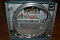
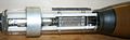
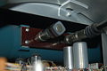
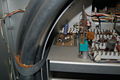
Rigid Coax Delay Line
To allow viewing of the leading edge of pulses, there is a rigid coaxial 45 ns delay line between the input and the CRT.

Note that 45 nanoseconds is an unusually short delay. For comparison, the delay line in a 547 is 170 ns. Keeping the delay short minimizes degradation of fast pulses, but it necessitates a trigger and sweep circuit with quick response.
A 519 can also be used with a pretrigger pulse generator like the 111.
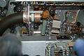
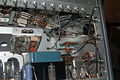
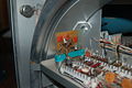
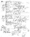
Trigger and Sweep
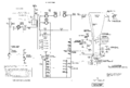
The sweep is triggered using a 20 mA, 4 pF tunnel diode. The horizontal deflection ramp signal of a 519 is generated by a 4CX250F external anode, radial-beam tube that is cooled by forced air sent from a blower through a duct.
The total accelerating voltage of the 519 is 24 kV.
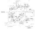
The 519 contains a calibration step generator that produces voltage steps with 100 picosecond rise time, and a rate generator that generates pulses with 500 ps rise times. The step generator utilizes a charged line which is discharged through a reed relay, while the rate generator uses a transistor in avalanche configuration. The reed relay in the step generator is tuned in part by listening to it.
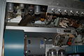
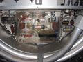
Unusual Physical Construction
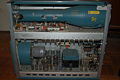
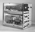
The physical construction and styling of the 519 differs from that of the other Tek scopes of the same period. There are multiple reasons for this. First, it has an unusually long CRT. Also, the large 125 Ω coaxial delay line (seen in the photo) had to fit inside the cabinet.
Finally, the 519 has an extra-large power transformer and a large blower for the 4CX250 tube. The mass of these extra components necessitated a larger, sturdier cabinet than, for example, the 545. The sheet aluminum used in the case of the 519 is thicker than that of the other Tek scopes of the period. The 519 weighs 99 pounds and consumes 650 watts.
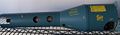
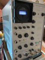
Different CRT Bezels
The 519 came with two different bezels. Pictured in Tek Catalog 20 through 26 is the early version which was actually a camera mount designed to be compatible with the C19 camera. It had a unique removable part with a graticule that could be slid down such that it would not be in between the CRT beam and the camera lens. Most of the non-used area of the CRT faceplate was covered by the black plastic material of the graticule cover. This graticule cover was changed slightly as is shown in the pictures of the 519 in Tek Catalogs 27 and later. It still was designed to mount the C19 camera. (For what reason was the bezel design changed?)
The 519 is probably the only Tek scope to come standard with a camera mount for a bezel. You had to buy camera mounting frames as accessories for the other scopes.
Production
Early 519's in the '61-'66 period were calibrated in Plant 2 in a group managed by Bob Randall. Three of the men calibrating 519's in that period were Stan Griffiths, Dick Bellamy, and John A. (What is John's last name?) During this period, Cliff Moulton would visit the calibration operation to answer any questions that would arise as the scopes were being prepared for shipment to customers.
Later 519's were calibrated at Plant 2 Test-Final in a group managed by Jack Lyngdal. Two of the calibration people that worked there were Norm Jenkins and Jack. (What is Jack's last name?) Another man who calibrated 519's in this later period was Mark Balcom.
The distributed deflection plate delay network had to be hand-trimmed, which was done prior to putting it inside the CRT envelope. It is possible that this was done using a TDR.
519C: A 3 GHz Version of the 519
Tektronix Catalog 22 (mid'63-mid'64) refers to a modified (MOD 795) 519 with response extended to 3 GHz:
DC-to-3 GIGACYCLE OSCILLOSCOPE: This modified Type 519 Oscilloscope incorporates a coaxial-deflection crt to achieve a risetime of 0.13nsec, corresponding to a 3000-Mc bandwidth. Deflection factor is approximately 180v/cm. Usable viewing area is 2x4 cm. Consult your FE to learn about the advantages, limitations, and delivery time on this or other modified instruments."
A 1983 IEEE Transactions on Nuclear Science paper includes a chart that mentions in Figure 10 the 3 GHz 519C introduced in 1963. The 519C was sold to Lawrence Livermore Labs and the Nuclear Test Site. The 519C uses the T5192 CRT.
- 519 manual (DJVU)
- Tektronix 519 in 1968 Catalog (PDF)
The 519 came with a set of adapters performing various functions such as interfacing the 125 Ω input impedance of the 519 with the more common 50 Ω impedance of many cables and instruments. One example is the 017-0019-00.
See Also
Pictures
-

519 adapter kit
-
519 adapter kit case
-
-
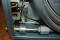
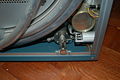
Delay line around the EHT section
-
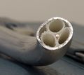
Cross section of Spir-o-line rigid coax (delay line)
-
CRT deflection trimmers*
-
Drawing from Devere book
-
Blower and duct
-
Sweep tube and duct
-
Vertical terminator
-
Trigger pickoff
-
-
-
-
-
high voltage power supply
-
-
-
-
Rate Generator (early)
-
Rate Generator (late)
-
Power Supply
-
Heater Supply and Wiring
-
Timebase Generator
-
Timing Switch
-
Timebase Gate and Unblanking
-
CRT Circuit
-
Timebase Trigger and Holdoff
-
Calibration Step Generator
-
Trigger Switch and Vertical Delay
-
-
-
-

-

-

Homebrew Mount for DSLR
-
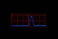
800 ps (FWHM) pulse from Tek 109 pulse generator, repetitive, 2 ns/div.
-
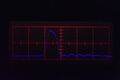
800 ps (FWHM) pulse from Tek 109 pulse generator, 2 ns/div single shot taken with Nikon D3s
-
-
-
-
-
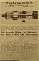
February 1, 1963 Tekweek referencing the T519C


- CRT photo courtesy of collection.archivist.info
- See Oscilloscope Cathode-Ray Tubes by Chuck Devere, page 30-35.
- See Tim Koeth's Page on the Tektronix 519
Components
Some Parts Used in the 519
| Part | Part Number(s) | Class | Description | Used in |
|---|---|---|---|---|
| 120-0186-00 | 120-0186-00 | Discrete component | power transformer | 519 |
| 4CX250F | 154-0300-00 | Vacuum Tube (Tetrode) | beam power tetrode | 519 |
| 6DJ8 | 154-0187-00 • 154-0305-00 | Vacuum Tube (Dual Triode) | dual triode | 111 • 132 • 161 • 310A • 316 • 317 • 502 • 502A • 503 • 504 • 506 • 515 • 516 • 519 • 526 • 529 • RM529 • 533 • 535 • 536 • 543 • 544 • 545 • 545A • 545B • 546 • 547 • 549 • 555 • 556 • 561A • 561S • 564 • 565 • 567 • 581 • 581A • 585 • 585A • 661 • 1A4 • 1S1 • 60 • 2A60 • 63 • 2A63 • 67 • 2B67 • 3A1 • 3A1S • 3A2 • 3A3 • 3A6 • 3A7 • 72 • 3A72 • 75 • 3A75 • 4S2 • 51 • 3B1 • 3B1S • 3B2 • 3B3 • 3B4 • 3M1 • 3S76 • 3T77 • 3T77A • 9A1 • 9A2 • 1121 • 80 • 81 • 82 • 86 • B • O • W • Z • Telequipment D56 • Telequipment S32A • Telequipment D52 • S-311 • Telequipment TD51 • Telequipment S52 • Telequipment S51 • Telequipment Type A • TU-4 |
| 6G11 | 154-0660-00 | Vacuum Tube (Pentode) | double sharp cut-off beam power pentode | 125 • 132 • 519 • 067-0502-01 • 050-0551-00 |
| T5191 | 154-0356-00 • 154-0308-00 | CRT | 1 GHz CRT | 519 |
| T5192 | CRT | CRT | 519 |