User:Peter
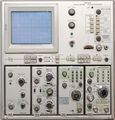
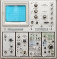
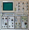
Scopes
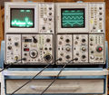
Other Instruments
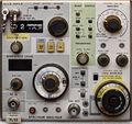
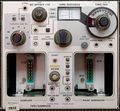
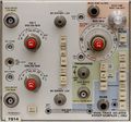
Plugins
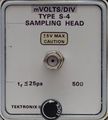
Probes and other gear
-
P6451 probe internal, PCB front
-
P6451 probe internal, PCB back
Screen shots
-
Faster-than-light beam on 7104? Using a 067-0587-02 calibration fixture at maximum amplitude produces this trace spanning 1.2 Div horizontally at 200 ps/Div and 8 Div vertically. Trace length is (1.2² + 8²)½ × 8.5 mm = 68.8 mm, travelled in 1.2 × 200 ps = 240 ps. Apparent speed is therefore 68.8×10⁻³ / 240×10-12 m/s or 2.86×10⁸ m/s. Very near miss ...
-
7104 rise time measurement. 150 ps risetime pulse from 067-0587-02 at 100 Hz repetition rate. Measured 240 ps (corrected for 150 ps fixture rise time: 190 ns = 1.8 GHz)
-
7104 rise time measurement as before, 1000 Hz repetition rate at same brightness settings.
-
7104 recording a single shot pulse (from 067-0587-02) at 200 ps/Div. Camera: Nikon D7000, 50 mm f/1.4, ISO 3200, 1/2 s. CRT filter not removed.
-
7104 recording 1 GHz sine, single shot at 500 ps/Div. Camera: Nikon D7000, 50 mm f/1.4, ISO 3200, 1/2 s. CRT filter not removed. CRT amplification loss is evident around the center line.
-
BC337 on 7CT1N
-
P6230 Rise time without ground lead: 9.2 * 20 ps = 184 ps (equiv. to 1.9 GHz bandwidth)
-
P6230 Rise time - Effect of using the "low inductance" ground lead - rise time 400 ps, bandwidth 875 MHz
-
P6230 Rise time - Using the 250 mm alligator ground lead - severe pulse distortion, rise time ~3 ns (115 MHz)!
-
Classic readout board diagnostic display
-
Tektronix 067-0587-02, gain mode, in horizontal slot
-
Tektronix 067-0587-02, gain mode, in vertical slot
-
7B85 used for rise time measurement
-
7B85 used for rise time measurement
-
7B85 used for pulse width measurement
-
7B85 used for pulse period measurement
-
7B85 used for pulse period measurement
-
7S12 as a sampler displaying a 1 GHz signal (hi-res mode / storage)
-
7S12 as a sampler displaying a 1 GHz signal (hi-res mode / storage)
-
7S12 as a sampler displaying a 1 GHz signal (normal mode / non-storage)
-
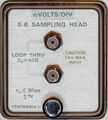
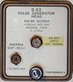
7S12 displaying the incident pulse from an S-52 (nom. < 25 ps) through an S-6 head (nom. < 30 ps)
-
sub-millivolt triangle signal displayed through 7A22, BW=1 kHz
-
sub-millivolt triangle signal displayed through 7A22, BW=10 kHz
-
sub-millivolt triangle signal displayed through 7A22, BW=100 kHz
-
sub-millivolt triangle signal through 7A22, BW=1 MHz
-
Measuring diode reverse recovery
-
BAT41 diode reverse recovery, 20 mA/Div
-
Tunnel diode quick check example using the method from Service Scope 49. Right beam is zoomed with delayed timebase to show step speed.
-
308 display, timing mode (binary counter example)
-
308 display, state mode (binary counter example)


