475: Difference between revisions
No edit summary |
No edit summary |
||
| (32 intermediate revisions by 10 users not shown) | |||
| Line 1: | Line 1: | ||
{{Oscilloscope Sidebar | | {{Oscilloscope Sidebar | ||
|manufacturer=Tektronix | |||
summary=Portable 200 MHz dual-trace scope | | |series=400-series scopes | ||
image=Tek 475 square sin.jpg | | |model=475 | ||
caption= Tektronix 475 | | |summary=Portable 200 MHz dual-trace scope | ||
introduced=1972 | | |image=Tek 475 square sin.jpg | ||
discontinued=1983 | | |caption= Tektronix 475 | ||
manuals= | |introduced=1972 | ||
|discontinued=1983 | |||
|designers=Leon Orchard;Luis Navarro;Bob Shand;Jim Hinze;Jim Godwin;Les Larson;Steve Tosh;Jim Woo;Ken Holland;Bill Mark;George Ermini;Dennis Braatz | |||
|manuals= | |||
'''475''' | '''475''' | ||
* [ | * [[Media:070-1333-00.pdf|Tektronix 475 Operators Manual]] (OCR, 14MB, good quality) | ||
* [ | * [[Media:070-1332-00.pdf|Tektronix 475 Service Manual]] (65MB, OK quality, needs re-OCR) | ||
* [[Media:TB-9-6625-2240-35.pdf|475 calibration (Army) (OCR) | * [[Media:070-1862-00.pdf|Tektronix 475 with Option SN B250,000-up]] (165MB) | ||
* [[Media:070- | * [[Media:070-2039-00.pdf|Tektronix 475/DM44 Operators Manual]] (16MB) | ||
* [[Media:tek_475_tek.pdf|Tektronix 475 Service Manual]] (65MB, OK quality) | |||
* [[Media:Tektronix_475_Oscilloscope_Service_Manual.pdf|Tektronix 475 Service Manual]] (108MB, good quality) | |||
* [[Media:TB-9-6625-2240-35.pdf|475 calibration (Army)]] (OCR) | |||
* [[Media:070-1739-01.pdf|475 and DM43/DM40 Instruction Manual]] | |||
'''475A''' | '''475A''' | ||
* [[Media:070-2163-00.pdf|Tektronix 475A-DM44 Oscilloscope Instruction Manual (OCR | * [[Media:070-2163-00.pdf|Tektronix 475A-DM44 Oscilloscope Instruction Manual]] (OCR) | ||
* [[Media:070-2162-00.pdf|Tektronix 475A Manual (11MB | * [[Media:070-2162-00.pdf|Tektronix 475A Service Manual]] (11MB) | ||
* [[Media:tek_475a_block_diagram.pdf|Tektronix 475A Schematics ( | * [[Media:tek_475a_block_diagram.pdf|Tektronix 475A Schematics]] (needs re-OCR) | ||
* [ | * [[Media:tek_475a_schematics.pdf|Tektronix 475A Schematics]] | ||
'''Modifications''' | '''Modifications''' | ||
* [[Media:050-1558-00.pdf|Modification: U3165 Replacement]] | * [[Media:050-1558-00.pdf|Modification: U3165 Replacement]] | ||
* [[Media:062-2784-00.pdf|067-0676-00 Vertical Insertion Unit for 475 Datasheet ( | * [[Media:062-2784-00.pdf|067-0676-00 Vertical Insertion Unit for 475 Datasheet]] (needs OCR) | ||
'''History''' | '''History''' | ||
* [[Media:Tek 465 and 475 marketing sales release.pdf|Tektronix 465 and 475 Marketing Sales Release | * [[Media:Tek 465 and 475 marketing sales release.pdf|Tektronix 465 and 475 Marketing Sales Release]] | ||
* [[Media:tek_475a_msr.pdf|Tektronix 475A Marketing Sales Release ( | * [[Media:tek_475a_msr.pdf|Tektronix 475A Marketing Sales Release]] (needs re-OCR) | ||
}} | }} | ||
The '''Tektronix 475''' is a portable dual-trace oscilloscope with dual time-bases similar to the [[465]], | The '''Tektronix 475''' is a portable dual-trace oscilloscope with dual time-bases similar to the [[465]], | ||
but with 200 MHz bandwidth and a maximum vertical sensitivity of 2 mV/Div. | but with 200 MHz bandwidth and a maximum vertical sensitivity of 2 mV/Div. | ||
It is all solid-state except for the CRT. | It is all solid-state except for the CRT. It was introduced in November 1972. | ||
It was introduced in November 1972. | |||
The military variant is called OS-261 C(v)1/0, which has a DC/DC converter (12/24V input) on board. | |||
A revised version, the 475A ([[introduced in 1977]]), has 250 MHz bandwidth and a maximum vertical sensitivity of 5 mV/Div. | |||
The [[1106]] is a battery pack for the 475. | The [[1106]] is a battery pack for the 475. | ||
The optional [[DM44]] multimeter attaches to the top of the instrument. | The optional [[DM44]] multimeter attaches to the top of the instrument. | ||
From [[Media:Tekscope 1972 V4 N5 Sep 1972.pdf|Tekscope Vol. 4 No. 5, 1972]]: | |||
<blockquote> | |||
Electrical design team [...] for the 475 under the leadership of [[Jim Hinze]] was: [[Jim Godwin]], [[Les Larson]], [[Steve Tosh]], and [[Jim Woo]]. | |||
</blockquote> | |||
{{BeginSpecs}} | {{BeginSpecs}} | ||
{{Spec | Bandwidth | 200 MHz (475), AC cutoff 10 Hz, switchable BW limit 20 MHz }} | {{Spec | Bandwidth | 200 MHz (475), AC cutoff 10 Hz, switchable BW limit 20 MHz }} | ||
{{Spec | Rise time | 1.75 ns (475) }} | {{Spec | Rise time | 1.75 ns (475) }} | ||
{{Spec | Deflection | 2 mV/Div to 5 V/Div, | {{Spec | Deflection | 2 mV/Div to 5 V/Div, 1−2−5 }} | ||
{{Spec | Cascaded mode | 400 μV/Div, 50 MHz with CH1 input connected to CH2 VERT SIG OUT }} | {{Spec | Cascaded mode | 400 μV/Div, 50 MHz with CH1 input connected to CH2 VERT SIG OUT }} | ||
{{Spec | Time base | 10 ns/Div to 500 ms/Div, | {{Spec | Time base | 10 ns/Div to 500 ms/Div, 1−2−5, and ×10 magnifier }} | ||
{{Spec | Input impedance | 1 MΩ // 20 pF }} | {{Spec | Input impedance | 1 MΩ // 20 pF }} | ||
{{Spec | Triggering | 0.3 Div (int) or 50 mV (ext) to 40 MHz, increasing to 1.5 Div/250 mV at 200 MHz; AC coupling >60 Hz; LF REJ >50 kHz, HF REJ <50 kHz }} | {{Spec | Triggering | 0.3 Div (int) or 50 mV (ext) to 40 MHz, increasing to 1.5 Div/250 mV at 200 MHz; AC coupling >60 Hz; LF REJ >50 kHz, HF REJ <50 kHz }} | ||
| Line 52: | Line 66: | ||
{{Spec | Calibrator | 1 kHz, 30 mA / 300 mV square wave }} | {{Spec | Calibrator | 1 kHz, 30 mA / 300 mV square wave }} | ||
{{Spec | Outputs | CH2 Vert Signal Out, 20 mV/Div into 1 MΩ or 10 mV/Div into 50 Ω; A and B +GATE OUT, +5 V; [[LEMO S-series connector|Probe power jack]] }} | {{Spec | Outputs | CH2 Vert Signal Out, 20 mV/Div into 1 MΩ or 10 mV/Div into 50 Ω; A and B +GATE OUT, +5 V; [[LEMO S-series connector|Probe power jack]] }} | ||
{{Spec | CRT | 8 × 10 cm², P31 phosphor (P11 opt.) }} | {{Spec | CRT | 8 × 10 cm², P31 phosphor (P11 opt.), [[154-0677-00]] }} | ||
{{Spec | Power | 110, 115, 120, 220, 230 or 240 V<sub>AC</sub> ±10%, 48-440 Hz, max. 100 W }} | {{Spec | Power | 110, 115, 120, 220, 230 or 240 V<sub>AC</sub> ±10%, 48-440 Hz, max. 100 W }} | ||
{{EndSpecs}} | {{EndSpecs}} | ||
| Line 65: | Line 79: | ||
* The New Look in Portables, in [[Media:Tekscope 1972 V4 N5 Sep 1972.pdf|Tekscope Vol. 4 No. 5, 1972]] | * The New Look in Portables, in [[Media:Tekscope 1972 V4 N5 Sep 1972.pdf|Tekscope Vol. 4 No. 5, 1972]] | ||
* [http://www.amplifier.cd/Test_Equipment/Tektronix/Tektronix_other/475.htm Tek 475] / [http://www.amplifier.cd/Test_Equipment/Tektronix/Tektronix_other/475A_DM44.htm Tek 475A] @ amplifier.cd | * [http://www.amplifier.cd/Test_Equipment/Tektronix/Tektronix_other/475.htm Tek 475] / [http://www.amplifier.cd/Test_Equipment/Tektronix/Tektronix_other/475A_DM44.htm Tek 475A] @ amplifier.cd | ||
* [https://www.youtube.com/watch?v=WPgkVThknYo Tek 475A / DM44 repair] by vintageTek Museum @ YouTube | |||
* [https://www.youtube.com/watch?v=2SESaF7Ibbw Tek 475A in operation] @ YouTube | * [https://www.youtube.com/watch?v=2SESaF7Ibbw Tek 475A in operation] @ YouTube | ||
* [https://www.youtube.com/watch?v=wfw60QmUp_A Tektronix 475A and DM44 Repair Power Supply and Logic] by Zenwizard Studios @ YouTube | |||
* [https://www.youtube.com/watch?v=KzVMbhytWOg Tektronix 475A and DM44 Power Supply and Tube Alignment] @ Zenwizard Studios YouTube | |||
* [https://www.youtube.com/watch?v=gEXYRPNohyA 151-0367-00 Guaranteed Bad Parts] @ Zenwizard Studios YouTube | |||
* [https://www.youtube.com/watch?v=gtDnTN14JL0 Tektronix 475A Vertical Alignment and One Last Power Supply Issue] @ Zenwizard Studios YouTube | |||
* [https://www.youtube.com/watch?v=tw55DrUR8s8 Tektronix 475A Trigger Section Alignment] @ Zenwizard Studios YouTube | |||
* [https://www.youtube.com/watch?v=5fGnnTfDNPA Tektronix DM44 & 475A Horizontal Alignment] by Zenwizard Studios @ YouTube | |||
* [[050-0674-00|Handle Replacement Modification Kit]] | * [[050-0674-00|Handle Replacement Modification Kit]] | ||
| Line 83: | Line 106: | ||
Tek_475A_Time-Freq.jpg | 475A Time/Frequency Measurement with [[DM44]], HP Frequency Counter used for Verifying [[DM44]] Output. | Tek_475A_Time-Freq.jpg | 475A Time/Frequency Measurement with [[DM44]], HP Frequency Counter used for Verifying [[DM44]] Output. | ||
Tek 475a rear.jpg|475A rear | Tek 475a rear.jpg|475A rear | ||
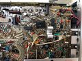
475A_A9-Interface_board.jpg | 475A A9 Interface | Tek_OS_261_rear.jpg | 475 (OS-261 C) rear, with DC-Input | ||
475A_A9-Interface_board.jpg | 475A A9 Interface board | |||
475A_A6_Fan_motor.jpg |475A A6 & Fan Motor | 475A_A6_Fan_motor.jpg |475A A6 & Fan Motor | ||
Tek_475A_A7Board.jpeg |475A A7 Timing board | |||
475A_A9-PowerSupply.jpg | 475A Power Supply Section of A9 | 475A_A9-PowerSupply.jpg | 475A Power Supply Section of A9 | ||
475A_DMM44_Board.jpg | 475A with [[DM44]] Board on top | 475A_DMM44_Board.jpg | 475A with [[DM44]] Board on top | ||
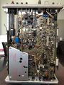
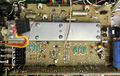
475A_A3-Vertical_Preamp.jpg | 475A A3 Vertical Preamp | 475A_A3-Vertical_Preamp.jpg | 475A A3 Vertical Preamp board | ||
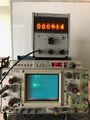
Tek475DM44 1khz.jpg | 475/DM44 measuring a 1 kHz sine wave | |||
Tek475DM44 10khz.jpg | 475/DM44 measuring a 10 kHz sine wave | |||
Tek475DM44 100khz.jpg | 475/DM44 measuring a 100 kHz sine wave | |||
</gallery> | </gallery> | ||
===475M=== | |||
<gallery> | |||
Tek 475m 1.jpg | |||
Tek 475m 2.jpg | |||
Tek 475m 3.jpg | |||
Tek 475m 4.jpg | |||
Tek 475m 5.jpg | |||
Tek 475m 6.jpg | |||
Tek 475m 7.jpg | |||
</gallery> | |||
{{Custom ICs|475}} | |||
{{Custom ICs|475A}} | |||
[[Category:400 series scopes]] | [[Category:400 series scopes]] | ||
Revision as of 13:01, 12 October 2022

The Tektronix 475 is a portable dual-trace oscilloscope with dual time-bases similar to the 465, but with 200 MHz bandwidth and a maximum vertical sensitivity of 2 mV/Div. It is all solid-state except for the CRT. It was introduced in November 1972.
The military variant is called OS-261 C(v)1/0, which has a DC/DC converter (12/24V input) on board.
A revised version, the 475A (introduced in 1977), has 250 MHz bandwidth and a maximum vertical sensitivity of 5 mV/Div.
The 1106 is a battery pack for the 475.
The optional DM44 multimeter attaches to the top of the instrument.
From Tekscope Vol. 4 No. 5, 1972:
Electrical design team [...] for the 475 under the leadership of Jim Hinze was: Jim Godwin, Les Larson, Steve Tosh, and Jim Woo.
Key Specifications
| Bandwidth | 200 MHz (475), AC cutoff 10 Hz, switchable BW limit 20 MHz |
|---|---|
| Rise time | 1.75 ns (475) |
| Deflection | 2 mV/Div to 5 V/Div, 1−2−5 |
| Cascaded mode | 400 μV/Div, 50 MHz with CH1 input connected to CH2 VERT SIG OUT |
| Time base | 10 ns/Div to 500 ms/Div, 1−2−5, and ×10 magnifier |
| Input impedance | 1 MΩ // 20 pF |
| Triggering | 0.3 Div (int) or 50 mV (ext) to 40 MHz, increasing to 1.5 Div/250 mV at 200 MHz; AC coupling >60 Hz; LF REJ >50 kHz, HF REJ <50 kHz |
| X bandwidth | 3 MHz |
| Z axis input | 5 Vp-p, 50 MHz |
| Calibrator | 1 kHz, 30 mA / 300 mV square wave |
| Outputs | CH2 Vert Signal Out, 20 mV/Div into 1 MΩ or 10 mV/Div into 50 Ω; A and B +GATE OUT, +5 V; Probe power jack |
| CRT | 8 × 10 cm², P31 phosphor (P11 opt.), 154-0677-00 |
| Power | 110, 115, 120, 220, 230 or 240 VAC ±10%, 48-440 Hz, max. 100 W |
Internals
The 475 uses a number of Tek-made integrated circuits, including the 155-0032-01 input preamplifier, 155-0085-00 input amplifier, 155-0078-00 vertical amplifier, 155-0091-00 channel switch, 155-0082-00 vertical output amplifier, and 155-0049-00 sweep control.
Links
- Lazy Electrons Tektronix 475A & DM44 Repair Page
- The New Look in Portables, in Tekscope Vol. 4 No. 5, 1972
- Tek 475 / Tek 475A @ amplifier.cd
- Tek 475A / DM44 repair by vintageTek Museum @ YouTube
- Tek 475A in operation @ YouTube
- Tektronix 475A and DM44 Repair Power Supply and Logic by Zenwizard Studios @ YouTube
- Tektronix 475A and DM44 Power Supply and Tube Alignment @ Zenwizard Studios YouTube
- 151-0367-00 Guaranteed Bad Parts @ Zenwizard Studios YouTube
- Tektronix 475A Vertical Alignment and One Last Power Supply Issue @ Zenwizard Studios YouTube
- Tektronix 475A Trigger Section Alignment @ Zenwizard Studios YouTube
- Tektronix DM44 & 475A Horizontal Alignment by Zenwizard Studios @ YouTube
Common Problems
- See 475/Repairs
Pictures
-

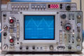
Tektronix 475A
-
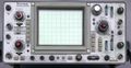
Tektronix 475A
-

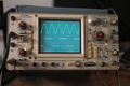
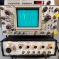
Tek 475 in mixed sweep ("MIX") horizontal mode
-
475A with DM44
-
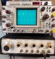
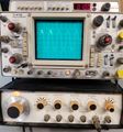
475
-

475 rear
-

475A with DM44
-
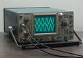
475
-
-
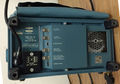
475A rear
-
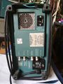
475 (OS-261 C) rear, with DC-Input
-
475A A9 Interface board
-
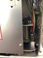
475A A6 & Fan Motor
-
475A A7 Timing board
-
475A Power Supply Section of A9
-
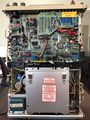
475A with DM44 Board on top
-

475A A3 Vertical Preamp board
-
475/DM44 measuring a 1 kHz sine wave
-
475/DM44 measuring a 10 kHz sine wave
-
475/DM44 measuring a 100 kHz sine wave


475M


Custom ICs used in the 475