661: Difference between revisions
No edit summary |
No edit summary |
||
| (32 intermediate revisions by 3 users not shown) | |||
| Line 1: | Line 1: | ||
{{Oscilloscope Sidebar | | {{Oscilloscope Sidebar | ||
|manufacturer=Tektronix | |||
summary=Sampling scope | | |series= | ||
image= | |model=661 | ||
caption=Tektronix 661 | | |summary=Sampling scope | ||
introduced=1961 | | |image=661_5T1A_4S1_front.JPG | ||
discontinued=(?) | | |caption=Tektronix 661 | ||
manuals= | |introduced=1961 | ||
* [ | |discontinued=(?) | ||
* [ | |designers=Norm Winningstad,Chuck Edgar,George Frye | ||
* [ | |manuals= | ||
* [http:// | * [[Media:070-324.pdf|Tektronix 661 Manual 070-324]] (early) | ||
* [ | * [[Media:070-0324-01.pdf|Tektronix 661 Manual 070-0324-01]] (late) | ||
* [[Media:tek_661_4s1_5t1_preliminary.pdf|Tek 661 4S1 5T1 Preliminary Manual]] | |||
* [ | <small> | ||
'''Alternate copies''' | |||
* [http://bama.edebris.com/manuals/tek/661 Tektronix 661 @ BAMA] | |||
* [ | |||
* [ | '''Calibration''' | ||
* [[Media:tek_661_factory_cal_proc.pdf|Tektronix 661 Factory Calibration Procedure]] | |||
* [[Media:Tek 661 cal outline.pdf|Tektronix 661 Calibration Outline]] (PDF, OCR)]] | |||
'''Other''' | |||
* [[Media:Nucl_Instrum_Methods_TD_Induct_effects_1968.pdf|Inductance Effects on Capacitive Loading of a Tunnel Diode]] | |||
* [[Media:Ragsdale_661_1963.pdf|Self-Sampling System for Measurement of Picosecond Pulse Characteristics]], R.Ragsdale, 1963 | |||
</small> | |||
}} | }} | ||
The '''Tektronix 661''' is a [[sampling oscilloscope]] that was [[introduced in 1961]]. | The '''Tektronix 661''' is a [[sampling oscilloscope]] that was [[introduced in 1961]]. | ||
It accepts two plug-ins, a sampling unit and a timing unit. | It accepts two plug-ins, a sampling unit and a timing unit. | ||
{{MissingSpecs}} | |||
==History== | |||
The 661 project was led by [[Norm Winningstad]]. | |||
In "Winning with People: The First 40 Years of Tektronix", Marshall Lee writes: | |||
<blockquote> | |||
During the early stages of the transition from tubes to transistors, | |||
however, computer research focused on emitter-coupled logic circuits, or ECL circuits, | |||
which proved much faster than conventional circuits, but also demanded higher-speed measuring instruments, | |||
which meant a much wider bandwidth. | |||
In response to ECL research, by 1962 Winningstad's group had produced the Type 661 sampling oscilloscope, | |||
which provided the answer to high speed and screen resolution. | |||
</blockquote> | |||
In addition to Winningstad, [[Chuck Edgar]] and [[George Frye]] worked on the 661 design. | |||
==Plug-ins== | |||
Four sampling units were made: | Four sampling units were made: | ||
* [[4S1]] (0.35 ns rise time) | * [[4S1]] (0.35 ns rise time) | ||
* [[4S2 | * [[4S2]] (0.1 ns rise time) | ||
* [[4S2A]] (90 ps rise time) | |||
* [[4S3]] (uses [[P6038]] sampling probes) | * [[4S3]] (uses [[P6038]] sampling probes) | ||
| Line 32: | Line 57: | ||
* [[5T1A]] | * [[5T1A]] | ||
* [[5T3]] | * [[5T3]] | ||
There is also a set of calibration fixtures, [[067-0066-00]], consisting of one Vertical Test Load Unit and one Sweep Test Load Unit plug-in, but these were likely internal-only products for use in production and service as the 067-0066-00 manual says that ''067-0066-00 Test Load Units are not required for calibration of 661s in the field''. | |||
== Inter-module signals == | == Inter-module signals == | ||
| Line 39: | Line 66: | ||
The other cable sends the "start sample signal" from the timing unit to the sampling unit, telling it when to sample. | The other cable sends the "start sample signal" from the timing unit to the sampling unit, telling it when to sample. | ||
The connectors used for the inter-module coaxial connections were made by Gremar. | The connectors used for the inter-module coaxial connections were made by Gremar. | ||
is a [[Gremar connector|Gremar 8212A]]. The connector on the scope side is a Gremar 8205A. | The connector on the plug-in side is a [[Gremar connector|Gremar 8212A]]. | ||
When operating one or both of the plug-ins outside of the 661, the sampling unit still | The connector on the scope side is a Gremar 8205A. | ||
needs the | When operating one or both of the plug-ins outside of the 661, | ||
the timing unit can be fed an external trigger signal via the timing unit's front panel. | |||
However, the sampling unit still needs the start sample signal from the timing unit. | |||
The Gremar extension cable, part number 012-070 (shown below) enables that. | |||
== Triggering modes == | == Triggering modes == | ||
A 661 can be triggered in at least four distinct modes: | A 661 can be triggered in at least four distinct modes: | ||
* The 4S1 uses a trigger pickoff transformer to produce the internal trigger signal that can trigger the timing unit. | * The 4S1 uses a trigger pickoff transformer to produce the internal trigger signal that can trigger the timing unit. The 4S1 is the only 661 sampling unit that produces an internal trigger signal. | ||
* An external trigger signal can be fed to the timing unit via its front panel. | * An external trigger signal can be fed to the timing unit via its front panel. | ||
* The timing unit can be operated in in free-running mode and the resulting pulse signal can be the stimulus for the device under test. This mode is similar to a TDR. | * The timing unit can be operated in in free-running mode and the resulting pulse signal can be the stimulus for the device under test. This mode is similar to a TDR. | ||
| Line 59: | Line 89: | ||
=== Power Supply === | === Power Supply === | ||
The power supply is typical of Tektronix scopes of early 1960s. | The power supply is typical of Tektronix scopes of early 1960s. | ||
The other supply voltages use the +300 V supply as their reference. | It is linear. | ||
All power rectifiers are silicon diodes. | |||
An [[OG3]] tube is used as a voltage reference for the +300 V supply. | |||
The other supply voltages use the +300 V supply as their reference. | |||
The +19 V and -19 V supplies use BJT-based regulators. | |||
The other regulators are tube-based. | The other regulators are tube-based. | ||
A 45 second delay tube is used so that plate voltage isn't applied to any tube in the 661 | |||
until the cathodes are hot. | |||
The 661 has a 137°F/58 °C [[thermal cutoff]]. | |||
In practice, it doesn't run hot. | |||
=== Indicator === | === Indicator === | ||
The indicator is a conventional X-Y indicator. | The indicator is a conventional X-Y indicator. | ||
The total CRT accelerating voltage is 3 kV. | |||
The 661 uses a [[T5030]] CRT with P2 [[phosphor]]. | |||
The vertical and horizontal amplifiers are essentially the same, | |||
each consisting of a two-stage differential amplifier. | |||
The first differential stage is made of a pair of [[OC170]] germanium PNP bipolar junction transistors | |||
driven single-endedly with emitters connected directly together (maximum voltage gain). | |||
The second differential stage is made of both triodes of a [[6DJ8]] tube with cathodes connected directly together (maximum voltage gain). | |||
The vertical and horizontal amplifiers have feedback loops around them that determine their gain. | The vertical and horizontal amplifiers have feedback loops around them that determine their gain. | ||
=== Calibrator === | === Calibrator === | ||
The amplitude/time calibrator is a Colpitts oscillator that uses a [[7119]] tube. | The amplitude/time calibrator is a Colpitts oscillator that uses a [[7119]] tube. | ||
from 100 kHz to 100 MHz and amplitudes from 1 mV to 1 V. The output is 50 Ω [[GR-874 connector]]. | It produces clippped sine waves at frequencies | ||
The signal from the calibration generator is available on the front panel and is also sent to the timing generator through the multi-pin plug-in connector. | from 100 kHz to 100 MHz and amplitudes from 1 mV to 1 V. | ||
The output is 50 Ω [[GR-874 connector]]. | |||
The signal from the calibration generator is available on the front panel | |||
and is also sent to the timing generator through the multi-pin plug-in connector. | |||
This allows the timing plug-ins to select "CAL" as a trigger source. | This allows the timing plug-ins to select "CAL" as a trigger source. | ||
In this mode, the calibration generator can be used as the stimulus for the device under test. | In this mode, the calibration generator can be used as the stimulus for the device under test. | ||
| Line 78: | Line 124: | ||
=== Delayed Pulse Generator === | === Delayed Pulse Generator === | ||
The delayed pulse generator is a [[tunnel diodes|tunnel diode]] circuit that produces a negative-going 250 mV pulse with a risetime of about 150 ps and a pulse width of about 400 ns. | The delayed pulse generator is a [[tunnel diodes|tunnel diode]] circuit that produces a negative-going 250 mV pulse | ||
When a timing unit (e.g., a 5T1) triggers, it sends a pulse through pin 10 of the J4 interconnect to the delayed pulse generator, which regenerates the pulse. | with a risetime of about 150 ps and a pulse width of about 400 ns. | ||
The output is a 50 Ω [[GR-874 connector]]. | |||
When a timing unit (e.g., a 5T1) triggers, it sends a pulse through pin 10 of the J4 interconnect | |||
to the delayed pulse generator, which regenerates the pulse. | |||
There are three versions of the 661 delayed pulse generator (serial numbers 101 through 2829, 2830 through 3459, 3460 and up). | There are three versions of the 661 delayed pulse generator (serial numbers 101 through 2829, 2830 through 3459, 3460 and up). | ||
All three versions use a 50 mA, 6 pF germanium tunnel diode to generate the actual output pulse. | All three versions use a 50 mA, 6 pF germanium tunnel diode to generate the actual output pulse. | ||
| Line 87: | Line 136: | ||
Based on the available schematics, the 661 appears to have been designed in 1961. | Based on the available schematics, the 661 appears to have been designed in 1961. | ||
:''During what years was it manufactured?'' | :''During what years was it manufactured?'' | ||
:''Why is it that the 661 has a dedicated high-speed coaxial interface between the sampling unit the timing unit while later 560-series sampling systems ([[3S2]], [[3T77A]], etc.) simply use the regular plug-in connector and mainframe wiring harness for routing trigger and timing signals between the two units?'' | :''Why is it that the 661 has a dedicated high-speed coaxial interface between the sampling unit the timing unit | ||
while later 560-series sampling systems ([[3S2]], [[3T77A]], etc.) simply use the regular plug-in connector | |||
and mainframe wiring harness for routing trigger and timing signals between the two units?'' | |||
Some 661s have a 41 pin [[Bendix connector]] on the rear panel, perhaps to allow the 661 to be interfaced to low speed data acquisition equipment or a computer. | Some 661s have a 41 pin [[Bendix connector]], J5, Tek part number 131-212, on the rear panel, | ||
perhaps to allow the 661 to be interfaced to low speed data acquisition equipment or a computer. | |||
This is essentially a pass-through from J2 & J3, the secondary multi-pin connectors on the vertical & horizontal plug-ins. | |||
These connectors carry switch position information (number, magnitude & units) and clock & gate pulses. | |||
Not all plug-ins had this 2nd connector; the [[5T1A]] does, while the [[5T3]] does not. | |||
The Tektronix [[012-064]] is a plug-in extension cable for the 661. | The Tektronix [[012-064]] is a plug-in extension cable for the 661. | ||
== Mechanical == | |||
The 661 is constructed similarly to late-model [[500-series scopes]]. | |||
The chassis is made of sheet aluminum. | |||
Most wiring is on [[Ceramic_Strips|ceramic strips]]. | |||
The side panels come off like those of a [[545|545B]] or [[547]]. | |||
The plug-ins of a 661 are incompatible with any other Tek scope, | |||
but the construction style is similar. | |||
The 661, like the 500-series scopes, uses Amphenol 26-series connectors | |||
for the electrical interface between plug-in and mainframe, but the | |||
661 uses a 24-pin version whereas the 500-series uses a 16-pin version | |||
of the connector. | |||
The sides and rear of the 661 painted identically to late-model | |||
500-series scopes, i.e., Tek-blue wrinkle. | |||
==Links== | ==Links== | ||
| Line 105: | Line 170: | ||
<gallery> | <gallery> | ||
Tek 661 s-52 rise.jpg|661 with [[4S1]] and [[5T3]] fed by [[S-52]]. 2 ns/div with 10x horizontal expansion gives 200 ps/div. | |||
661 5T1A 4S1 front.JPG | front view | |||
661_front.jpg | front view | |||
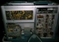
661_top_int.jpg | top internal view | 661_top_int.jpg | top internal view | ||
Tek 661 block.png|Block Diagram | |||
661_trace.jpg | trace with 10 samples/cm and 2× horizontal expansion | 661_trace.jpg | trace with 10 samples/cm and 2× horizontal expansion | ||
661_left_int.jpg | lleft internal view | 661_left_int.jpg | lleft internal view | ||
| Line 124: | Line 192: | ||
Tek 661 rear2.jpg|Rear panel of 661. J5 connector is on the upper left | Tek 661 rear2.jpg|Rear panel of 661. J5 connector is on the upper left | ||
Tek 661 rear J5 connector.jpg|J5 connector on rear panel of 661 | Tek 661 rear J5 connector.jpg|J5 connector on rear panel of 661 | ||
Tek 661 late sn delayed pulse2.png|Delayed pulse generator, final circuit version | |||
Tek 661 ad 1963.png|Ad from 1963 | |||
</gallery> | </gallery> | ||
{{Plugins|661}} | |||
==Components== | |||
{{Parts|661}} | |||
[[Category:Sampling scopes]] | [[Category:Sampling scopes]] | ||
[[Category:661 series scopes]] | [[Category:661 series scopes]] | ||
Latest revision as of 07:20, 25 October 2023

The Tektronix 661 is a sampling oscilloscope that was introduced in 1961. It accepts two plug-ins, a sampling unit and a timing unit.
Key Specifications
- please add
History
The 661 project was led by Norm Winningstad. In "Winning with People: The First 40 Years of Tektronix", Marshall Lee writes:
During the early stages of the transition from tubes to transistors, however, computer research focused on emitter-coupled logic circuits, or ECL circuits, which proved much faster than conventional circuits, but also demanded higher-speed measuring instruments, which meant a much wider bandwidth. In response to ECL research, by 1962 Winningstad's group had produced the Type 661 sampling oscilloscope, which provided the answer to high speed and screen resolution.
In addition to Winningstad, Chuck Edgar and George Frye worked on the 661 design.
Plug-ins
Four sampling units were made:
- 4S1 (0.35 ns rise time)
- 4S2 (0.1 ns rise time)
- 4S2A (90 ps rise time)
- 4S3 (uses P6038 sampling probes)
Three timing units were made:
There is also a set of calibration fixtures, 067-0066-00, consisting of one Vertical Test Load Unit and one Sweep Test Load Unit plug-in, but these were likely internal-only products for use in production and service as the 067-0066-00 manual says that 067-0066-00 Test Load Units are not required for calibration of 661s in the field.
Inter-module signals
The timing units use tunnel diode triggering. Two 50 Ω coaxial cables in the scope connect the sampling unit to the timing unit. One of these cables sends the "internal trigger signal" from the sampling unit to the timing unit. The other cable sends the "start sample signal" from the timing unit to the sampling unit, telling it when to sample.
The connectors used for the inter-module coaxial connections were made by Gremar. The connector on the plug-in side is a Gremar 8212A. The connector on the scope side is a Gremar 8205A. When operating one or both of the plug-ins outside of the 661, the timing unit can be fed an external trigger signal via the timing unit's front panel. However, the sampling unit still needs the start sample signal from the timing unit. The Gremar extension cable, part number 012-070 (shown below) enables that.
Triggering modes
A 661 can be triggered in at least four distinct modes:
- The 4S1 uses a trigger pickoff transformer to produce the internal trigger signal that can trigger the timing unit. The 4S1 is the only 661 sampling unit that produces an internal trigger signal.
- An external trigger signal can be fed to the timing unit via its front panel.
- The timing unit can be operated in in free-running mode and the resulting pulse signal can be the stimulus for the device under test. This mode is similar to a TDR.
- The calibration signal generator in the 661 can be used as trigger source, as described below.
Subsystems of the 661
Other than the two plug-ins, the 661 mainframe essentially consists of four subsystems:
- power supply
- indicator
- amplitude/time calibration signal generator
- delayed pulse generator
Power Supply
The power supply is typical of Tektronix scopes of early 1960s. It is linear. All power rectifiers are silicon diodes. An OG3 tube is used as a voltage reference for the +300 V supply. The other supply voltages use the +300 V supply as their reference. The +19 V and -19 V supplies use BJT-based regulators. The other regulators are tube-based. A 45 second delay tube is used so that plate voltage isn't applied to any tube in the 661 until the cathodes are hot. The 661 has a 137°F/58 °C thermal cutoff. In practice, it doesn't run hot.
Indicator
The indicator is a conventional X-Y indicator. The total CRT accelerating voltage is 3 kV. The 661 uses a T5030 CRT with P2 phosphor. The vertical and horizontal amplifiers are essentially the same, each consisting of a two-stage differential amplifier. The first differential stage is made of a pair of OC170 germanium PNP bipolar junction transistors driven single-endedly with emitters connected directly together (maximum voltage gain). The second differential stage is made of both triodes of a 6DJ8 tube with cathodes connected directly together (maximum voltage gain). The vertical and horizontal amplifiers have feedback loops around them that determine their gain.
Calibrator
The amplitude/time calibrator is a Colpitts oscillator that uses a 7119 tube. It produces clippped sine waves at frequencies from 100 kHz to 100 MHz and amplitudes from 1 mV to 1 V. The output is 50 Ω GR-874 connector. The signal from the calibration generator is available on the front panel and is also sent to the timing generator through the multi-pin plug-in connector. This allows the timing plug-ins to select "CAL" as a trigger source. In this mode, the calibration generator can be used as the stimulus for the device under test. In many situations, this eliminates the need for external triggering.
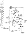
Delayed Pulse Generator
The delayed pulse generator is a tunnel diode circuit that produces a negative-going 250 mV pulse with a risetime of about 150 ps and a pulse width of about 400 ns. The output is a 50 Ω GR-874 connector. When a timing unit (e.g., a 5T1) triggers, it sends a pulse through pin 10 of the J4 interconnect to the delayed pulse generator, which regenerates the pulse. There are three versions of the 661 delayed pulse generator (serial numbers 101 through 2829, 2830 through 3459, 3460 and up). All three versions use a 50 mA, 6 pF germanium tunnel diode to generate the actual output pulse. In early 661 production, a 1N3130 tunnel diode was used. Then it was replaced by a TD1081. The circuit versions also differ in how they bias and trip the output tunnel diode.
Based on the available schematics, the 661 appears to have been designed in 1961.
- During what years was it manufactured?
- Why is it that the 661 has a dedicated high-speed coaxial interface between the sampling unit the timing unit
while later 560-series sampling systems (3S2, 3T77A, etc.) simply use the regular plug-in connector and mainframe wiring harness for routing trigger and timing signals between the two units?
Some 661s have a 41 pin Bendix connector, J5, Tek part number 131-212, on the rear panel, perhaps to allow the 661 to be interfaced to low speed data acquisition equipment or a computer. This is essentially a pass-through from J2 & J3, the secondary multi-pin connectors on the vertical & horizontal plug-ins. These connectors carry switch position information (number, magnitude & units) and clock & gate pulses. Not all plug-ins had this 2nd connector; the 5T1A does, while the 5T3 does not.
The Tektronix 012-064 is a plug-in extension cable for the 661.
Mechanical
The 661 is constructed similarly to late-model 500-series scopes. The chassis is made of sheet aluminum. Most wiring is on ceramic strips. The side panels come off like those of a 545B or 547. The plug-ins of a 661 are incompatible with any other Tek scope, but the construction style is similar. The 661, like the 500-series scopes, uses Amphenol 26-series connectors for the electrical interface between plug-in and mainframe, but the 661 uses a 24-pin version whereas the 500-series uses a 16-pin version of the connector. The sides and rear of the 661 painted identically to late-model 500-series scopes, i.e., Tek-blue wrinkle.
Links
- Reading Jim Williams: Scope Sunday #45
- A 661 can be seen in the Tektronix film on Transmission Lines.
Pictures
-
-
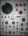
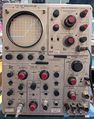
front view
-
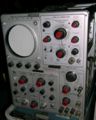
front view
-
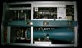
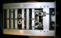
top internal view
-
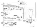
Block Diagram
-
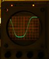
trace with 10 samples/cm and 2× horizontal expansion
-

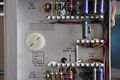
lleft internal view
-
right internal view
-
rear view (fan removed)
-
close-up of solder & inspection markings
-
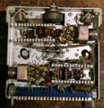
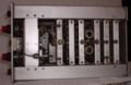
top view of 4S1
-
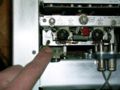
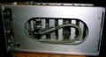
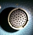
Coaxial interconnect from timing plug-in goes through the mainframe, into the 4S1, and ends here, at the sampler.
-
This is the sampler. The GaAs sampling diodes are arranged in a diamond shape and are directly connected to the socket from the delay line.
-
The delay line is a coil of coax going from the trigger pickoff to the sampler.
-
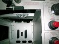
The 661 mainframe has two pieces of 50 Ω coax that connect the sampling unit bay to the timing unit bay. The plug-ins engage with these interconnects when inserted.
-
4S2 top view
-
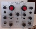
4S2 front view
-
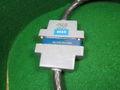
012-064 plug-in extension cable for 661
-
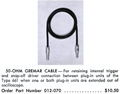
012-070 Gremar Extension Cable
-
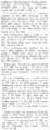
Mod described in June 1963 Service Scope regarding the delayed pulse generator
-
Rear panel of 661. J5 connector is on the upper left
-
J5 connector on rear panel of 661
-
Delayed pulse generator, final circuit version
-
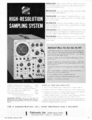
Ad from 1963


Some plug-ins / accessories compatible with 661
| Page | Manufacturer | Model | Description | Introduced | Discontinued |
|---|---|---|---|---|---|
| 067-0066-00 | Tektronix | 067-0066-00 | Calibration Fixture | 1961 | (?) |
| 4S1 | Tektronix | 4S1 | Dual channel sampling plugin | 1962 | (?) |
| 4S2 | Tektronix | 4S2 | Dual channel sampling plugin | 1962 | (?) |
| 4S2A | Tektronix | 4S2A | Dual channel sampling plugin | 1965 | (?) |
| 4S3 | Tektronix | 4S3 | 1 GHz dual-trace sampling plugin | 1963 | (?) |
| 5T1 | Tektronix | 5T1 | Sampling sweep unit | 1961 | (?) |
| 5T1A | Tektronix | 5T1A | Timing plugin | 1963 | (?) |
| 5T3 | Tektronix | 5T3 | Timing plugin | 1965 | (?) |
Components
Some Parts Used in the 661
| Part | Part Number(s) | Class | Description | Used in |
|---|---|---|---|---|
| 0G3 | 154-0291-00 | Gas Discharge Tube (Voltage regulator) | 85 V voltage reference | 132 • 506 • 547 • 560 • 561 • 561A • 561S • 564 • 565 • 567 • 661 • TU-4 • Z • Keithley 610 |
| 1N3130 | 152-0078-00 | Discrete component | 50 mA, 25 pF Germanium tunnel diode | 661 • 281 |
| 1N3719 | 152-0182-00 | Discrete component | 10 mA, 50 pF germanium tunnel diode | 422 • 661 • 7B92 • 7B92A |
| 6DJ8 | 154-0187-00 • 154-0305-00 | Vacuum Tube (Dual Triode) | dual triode | 111 • 132 • 161 • 310A • 316 • 317 • 502 • 502A • 503 • 504 • 506 • 515 • 516 • 519 • 526 • 529 • RM529 • 533 • 535 • 536 • 543 • 544 • 545 • 545A • 545B • 546 • 547 • 549 • 555 • 556 • 561A • 561S • 564 • 565 • 567 • 581 • 581A • 585 • 585A • 661 • 1A4 • 1S1 • 60 • 2A60 • 63 • 2A63 • 67 • 2B67 • 3A1 • 3A1S • 3A2 • 3A3 • 3A6 • 3A7 • 72 • 3A72 • 75 • 3A75 • 4S2 • 51 • 3B1 • 3B1S • 3B2 • 3B3 • 3B4 • 3M1 • 3S76 • 3T77 • 3T77A • 9A1 • 9A2 • 1121 • 80 • 81 • 82 • 86 • B • O • W • Z • Telequipment D56 • Telequipment S32A • Telequipment D52 • S-311 • Telequipment TD51 • Telequipment S52 • Telequipment S51 • Telequipment Type A • TU-4 |
| 7119 | 154-0340-00 | Vacuum Tube (Dual Triode) | dual triode | 067-0532-00 • 191 • 3A3 • 3B4 • 3B5 • 516 • 545B • 549 • 661 • Chemtrix 205 |
| OC170 | Discrete component | alloy-diffused Germanium PNP transistor | 321 • 661 | |
| SMTD907 | 152-0275-00 | Discrete component | 50 mA, 5 pF germanium tunnel diode | 280 • 661 |
| STD916 | 152-0098-00 | Discrete component | 10 mA, 90 pF tunnel diode | 556 • 565 • RM565 • 661 |
| T5030 | 154-0264-00 • 154-0265-00 • 154-0266-00 • 154-0267-00 • 154-0341-00 | CRT | CRT | 503 • 504 • 560 • 561 • 661 |
| TD1081 | 152-0099-00 • 152-0334-00 | Discrete component | 50 mA, 6 pF germanium tunnel diode | 280 • 661 • 017-0086-00 |