FG501: Difference between revisions
(-cat) |
(Added some more details) |
||
| (22 intermediate revisions by 4 users not shown) | |||
| Line 1: | Line 1: | ||
The | {{TM500 | mfg=Tektronix | type=FG501 | function=function generator | class=function generator | image=Tek fg501.JPG | introduced=1972 | discontinued=1993 | ||
|designers=Roger Stenbock | |||
|manuals= | |||
* [[Media:070-1431-01.pdf|Tektronix FG501 Manual]] (OCR) | |||
* [[Media:070-2957-00.pdf|Tektronix FG501A Manual]] | |||
<!-- | |||
* [https://w140.com/tek_fg501.pdf Tektronix FG501 Manual (PDF)] | |||
* [https://w140.com/smb/FG501A_SM.pdf Tektronix FG501A Manual (OCR, PDF)] | |||
--> | |||
}} | |||
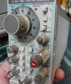
The TRIG OUT signal is available on the front panel via a [[BSM|BSM female connector]]. | |||
The FG501 is specified at a max frequency of 1 MHz, while the "A" model is specified at 2 MHz. The FG501 features seven different functions: Sine, Triangle, Square, +Ramp, -Ramp, 50%>duty square, 50%<duty. The Duty cycle of the Ramp and pulses (not square) are determined by the equation 1/2,,f,, where the veriable ,,f,, represents frequency. | |||
The "A" model features only 3 functions: Sine, Triangle, Square. But the other absent functions compensated with a variable symmetry function, effectively allowing the same functionality with only three functions. The "A" model also features an attenuator, not found in the non-"A" model. | |||
{{BeginSpecs}} | |||
{{SpecGroup | FG501 }} | |||
{{Spec | Frequency | 0.01 Hz to 1 MHz in decade steps}} | |||
{{Spec | Output | Max. 20 V<sub>p-p</sub> into high impedance, 10 V into 50 Ω (SN < B130000: 15/7.5 V)}} | |||
{{Spec | Offset | Max. ±7.5 V<sub>p-p</sub> into high impedance, 5 V into 50 Ω (SN < B130000: 5/2.5 V }} | |||
{{SpecGroup | FG501A }} | |||
{{Spec | Frequency | 0.002 Hz to 2 MHz in eight decade steps }} | |||
{{Spec | Output | Max. 30 V<sub>p-p</sub> (into high impedance) }} | |||
{{Spec | Attenuator | 60 dB in 20 dB steps, 20 dB variable }} | |||
{{Spec | Rise time | 25 ns }} | |||
{{SpecGroup | All models }} | |||
{{Spec | Signals | sine, square, triangle, ramp, pulse }} | |||
{{Spec | Features | | |||
* voltage controlled frequency input (1000:1 ratio) | |||
* triggering | |||
* variable phase control | |||
* symmetry variable from 5—95% | |||
* internal sweep generator, 3 decades, lin/log | |||
}} | |||
{{EndSpecs}} | |||
* [http:// | ==Links== | ||
* [ | * [[FG507]] - same specs as FG501A, added internal sweep generator | ||
* [http://www.barrytech.com/tektronix/tektm500/tekfg501.html FG501 @ barrytech.com] | |||
* [https://www.youtube.com/watch?v=B5M0QhbhXR4 Zenwizard Studios - Tektronix FG501A Repair and Calibration/Alignment] | |||
{{Documents|Link=FG501}} | |||
==Pictures== | |||
===FG501=== | |||
<gallery> | <gallery> | ||
Tek fg501.JPG | |||
FG-501-IMG_2733.JPG | |||
FG-501-IMG_2735.JPG | |||
FG-501-IMG_2736.JPG | |||
FG-501-IMG_2738.JPG | |||
</gallery> | </gallery> | ||
===FG501A=== | |||
<gallery> | |||
Tek fg501a 1.jpg | |||
Tek fg501a 2.jpg | |||
Tek fg501a 3.jpg | right interior | |||
Tek fg501a 4.jpg | left interior | |||
Tek fg 501a front.jpg | |||
Tek fg 501a right.jpg | right interior | |||
Tek fg 501a left.jpg | left interior | |||
Tek fg 501a rear.jpg | rear connector | |||
</gallery> | |||
==Components== | |||
{{Parts|FG501}} | |||
Latest revision as of 00:04, 29 February 2024

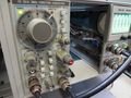
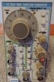
The Tektronix FG501 is a function generator plug-in for the TM500 system.
The TRIG OUT signal is available on the front panel via a BSM female connector. The FG501 is specified at a max frequency of 1 MHz, while the "A" model is specified at 2 MHz. The FG501 features seven different functions: Sine, Triangle, Square, +Ramp, -Ramp, 50%>duty square, 50%<duty. The Duty cycle of the Ramp and pulses (not square) are determined by the equation 1/2,,f,, where the veriable ,,f,, represents frequency. The "A" model features only 3 functions: Sine, Triangle, Square. But the other absent functions compensated with a variable symmetry function, effectively allowing the same functionality with only three functions. The "A" model also features an attenuator, not found in the non-"A" model.
Key Specifications
| — FG501 — | |
| Frequency | 0.01 Hz to 1 MHz in decade steps |
| Output | Max. 20 Vp-p into high impedance, 10 V into 50 Ω (SN < B130000: 15/7.5 V) |
| Offset | Max. ±7.5 Vp-p into high impedance, 5 V into 50 Ω (SN < B130000: 5/2.5 V |
| — FG501A — | |
| Frequency | 0.002 Hz to 2 MHz in eight decade steps |
| Output | Max. 30 Vp-p (into high impedance) |
| Attenuator | 60 dB in 20 dB steps, 20 dB variable |
| Rise time | 25 ns |
| — All models — | |
| Signals | sine, square, triangle, ramp, pulse |
| Features |
|
Links
- FG507 - same specs as FG501A, added internal sweep generator
- FG501 @ barrytech.com
- Zenwizard Studios - Tektronix FG501A Repair and Calibration/Alignment
Documents Referencing FG501
| Document | Class | Title | Authors | Year | Links |
|---|---|---|---|---|---|
| Tekscope 1972 V4 N3 May 1972.pdf | Article | TM500 series - A New Dimension in Plug-in Instrumentation | Bob Ragsdale | 1972 | TM500 system • TM501 • TM503 • FG501 • FG502 • RG501 • PG501 • SG502 • DC501 • DC502 • PS501 • PS502 • PS503 |
| 070-2088-00.pdf | Book | TM500 Series Rear Interface Data Book | 1975 | AF501 • AM501 • AM502 • DC501 • DC502 • DC503 • DC504 • DC505 • DC505A • DM501 • DM502 • FG501 • FG502 • FG503 • MR501 • PG501 • PG502 • PG505 • PG506 • PG508 • PS501 • PS502 • PS503 • PS503A • PS505 • RG501 • SC501 • SC502 • SG502 • SG503 • TG501 | |
| 070-2088-01.pdf | Book | TM500 Series Rear Interface Data Book | 1976 | AF501 • AM501 • AM502 • AM511 • DC501 • DC502 • DC503 • DC504 • DC505 • DC505A • DD501 • DM501 • DM502 • FG501 • FG502 • FG503 • FG504 • LA501 • MR501 • PG501 • PG502 • PG505 • PG506 • PG508 • PS501 • PS502 • PS503 • PS503A • PS505 • RG501 • SC501 • SC502 • SG502 • SG503 • SG504 • SW503 • TG501 • TR501 • TR502 |
Pictures
FG501


FG501A
-
-
-
right interior
-
left interior
-
-

right interior
-
left interior
-

rear connector


Components
Some Parts Used in the FG501
| Part | Part Number(s) | Class | Description | Used in |
|---|---|---|---|---|
| 151-0261-00 | 151-0261-00 | Discrete component | dual PNP transistor | AM501 • AM502 • CG5001 • CG551AP • FG501 • FG502 • FG503 • OF150 • OF151 • OF152 • OF235 • OS261 • RM502A • R1140 • R5030 • R5031 • R7912 • 067-0679-00 • 067-0807-00 • 1101 • 1140A • 1141 • 1142 • 1350 • 145 • 1450 • 1480 • 1481 • 1482 • 1485 • 1501 • 1801 • 1900 • 1910 • 1980 • 213 • 26A1 • 26A2 • 2620 • 285 • 3A9 • 3A10 • 3S1 • 3S2 • 3S5 • 3S6 • 432 • 434 • 4501 • 454 • 4601 • 4602 • 4610 • 4612 • 4620 • 4632 • 4634 • 4701 • 475 • 492 • 492A • 492AP • 494 • 494P • 496 • 496P • 5A13N • 5A20N • 5A21N • 5A22N • 5A26 • 5L4N • 502A • 5030 • 5031 • 576 • 690SR • 7A22 • 7A29 • 7B51 • 7B71 • 7J20 • 7L5 • 7S11 • 7S12 • 7912AD |