DM501: Difference between revisions
No edit summary |
No edit summary |
||
| (38 intermediate revisions by 8 users not shown) | |||
| Line 1: | Line 1: | ||
{{TM500 | mfg=Tektronix | type=DM501 | function=4½ digit | {{TM500 | mfg=Tektronix | type=DM501 | function=4½ digit multimeter | class=multimeter | image=Tek DM501.JPG | introduced=1972 | discontinued=1980 | | ||
manuals= | designers= |manuals= | ||
* [ | * [[Media:070-1446-00.pdf|Tektronix DM501 Manual]] | ||
}} | }} | ||
(See [[DM501A]] for the significantly different successor model.) | |||
It also has a temperature input, requiring the [[ | It also has a temperature input, requiring the [[P6058]] temperature probe with a 4-pin [[LEMO S-series connector]]. The manual states that ''certain NPN transistors such as a 2N2484 may be used as temperature sensors in place of the probe with little or no selection of the transistor''. | ||
The '''DM501 MOD718D''' variant replaced the temperature range with a 200 mV input range providing 10 μV resolution (see [[Media:Physical Measurements Handbook.pdf | Physical Measurements Handbook]]). | |||
{{BeginSpecs}} | {{BeginSpecs}} | ||
{{Spec | DC | {{Spec | DC Voltage | 2 V<sub>DC</sub> to 200 V<sub>DC</sub> in decade ranges (0.1% + 0.01% FS), 1000 V<sub>DC</sub> (0.1% + 0.02% FS); Input resistance 10 MΩ, CMRR >100 dB at DC, 80 dB at 60 Hz (1 kΩ unbal.), NMRR ≥30 dB at 60 Hz + 20 dB/decade }} | ||
{{Spec | AC Voltage | 2 V<sub>DC</sub> to 200 V<sub>AC</sub> in decade ranges, and 500 V<sub>AC</sub> (0.7% + 0.01% FS for sine inputs only); Input impedance 10 MΩ // ≤70 pF, CMRR unspecified }} | |||
{{Spec | DC Current | 2 mA to 2 A in decade ranges, 0.2% + 0.05% FS }} | |||
{{Spec | AC Current | 2 mA to 2 A in decade ranges, 0.6% + 0.05% FS (for 40 Hz to 1 kHz sine) }} | |||
{{Spec | Ohms | 2 kΩ to 20 MΩ in decade ranges, current 1 mA to 0.1 μA respectively; 0.3% (20 MΩ: 0.5%) + 0.01% FS }} | |||
{{Spec | AC | {{Spec | Temperature | –55°C to +125°C (±1.5°C), +125°C to 150°C (±2.5°C) }} | ||
{{Spec | DC | |||
{{Spec | AC | |||
{{Spec | | |||
{{Spec | Temperature | |||
{{EndSpecs}} | {{EndSpecs}} | ||
===Options=== | |||
* Option 1: Ordering without P6058 Temp Probe | |||
* Option 2: Without Temp Capability and Probe (visible by no ''Temp Out'' at the Front) | |||
==Links== | |||
* [https://www.youtube.com/watch?v=GaSy1MezeNs Tektronix DM501 Check in and Calibration] by Zenwizard Studios @ YouTube | |||
{{Documents|Link=DM501}} | |||
{{PatentLinks|DM501}} | |||
==Rear interface== | |||
The DM501 has a rear input, selectable by a front-panel button, on B28 (Hi) / A29 (Lo), and digit-serial BCD outputs (TTL), see below. | |||
The manual does not specify a limit to the input voltage on the rear interface but since this uses card-edge pins adjacent to logic output pins, sticking to the the DM501A specification (200 V peak / 100 V RMS) appears prudent. | |||
==Internals== | |||
The DM501 is precise to 4½ digits, but not accurate to 4½ digits. The combination of an ADC built from opamps and discretes combined with a noisy high-frequency isolated power supply make for barely achievable 3½ digit accuracy over all ranges. Every TM500 DVM after the 501 (including the [[DM501A]], the [[DM502]], and so on) used integrated A-to-D converters and a mains-frequency isolated power supply. | |||
==Pictures== | ==Pictures== | ||
<gallery> | <gallery> | ||
DM501 front.jpg | DM501 | DM501 front.jpg | DM501 | ||
DM501_open_left.jpg | DM501 open left side | |||
Tek_DM501_integrator_pcb-comp_side.jpg | DM501 integrator board | |||
DM501 1977.jpg | Two late DM501s with modified integrator boards | |||
Tek_DM501_integrator_pcb-solder_side.jpg | DM501 integrator board solder side | |||
DM501 rear interface.png | DM501 rear interface | |||
</gallery> | </gallery> | ||
==Components== | |||
{{Parts|DM501}} | |||
Latest revision as of 04:43, 31 October 2024
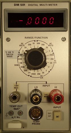
The Tektronix DM501 is a 4½ digit multimeter plug-in for the TM500 system.
(See DM501A for the significantly different successor model.)
It also has a temperature input, requiring the P6058 temperature probe with a 4-pin LEMO S-series connector. The manual states that certain NPN transistors such as a 2N2484 may be used as temperature sensors in place of the probe with little or no selection of the transistor.
The DM501 MOD718D variant replaced the temperature range with a 200 mV input range providing 10 μV resolution (see Physical Measurements Handbook).
Key Specifications
| DC Voltage | 2 VDC to 200 VDC in decade ranges (0.1% + 0.01% FS), 1000 VDC (0.1% + 0.02% FS); Input resistance 10 MΩ, CMRR >100 dB at DC, 80 dB at 60 Hz (1 kΩ unbal.), NMRR ≥30 dB at 60 Hz + 20 dB/decade |
|---|---|
| AC Voltage | 2 VDC to 200 VAC in decade ranges, and 500 VAC (0.7% + 0.01% FS for sine inputs only); Input impedance 10 MΩ // ≤70 pF, CMRR unspecified |
| DC Current | 2 mA to 2 A in decade ranges, 0.2% + 0.05% FS |
| AC Current | 2 mA to 2 A in decade ranges, 0.6% + 0.05% FS (for 40 Hz to 1 kHz sine) |
| Ohms | 2 kΩ to 20 MΩ in decade ranges, current 1 mA to 0.1 μA respectively; 0.3% (20 MΩ: 0.5%) + 0.01% FS |
| Temperature | –55°C to +125°C (±1.5°C), +125°C to 150°C (±2.5°C) |
Options
- Option 1: Ordering without P6058 Temp Probe
- Option 2: Without Temp Capability and Probe (visible by no Temp Out at the Front)
Links
- Tektronix DM501 Check in and Calibration by Zenwizard Studios @ YouTube
Documents Referencing DM501
Patents that may apply to DM501
| Page | Title | Inventors | Filing date | Grant date | Links |
|---|---|---|---|---|---|
| Patent US 3562464A | Cam actuated switch having movable and fixed contacts on circuit board | Howard Vollum • Willem H Verhoef • Tony Sprando | 1968-10-07 | 1971-02-09 | Cam switches • 2101 • 2701 • 2703 • 432 • 434 • 465 • 475 • 5A15N • 5A18N • 5A20N • 5A21N • 5A38 • 5A45 • 5B10N • 5B12N • 7A15 • 7A16A • 7A18 • 7A19 • 7A24 • 7A26 • 7B10 • 7B15 • 7B50 • 7B51 • 7B52 • 7B53A • 7B50A • 7B70 • 7B71 • 7B80 • 7B85 • 7B87 • 7B92 • 7B92A • 7D01 • 7D12 • 7D15 • 7J20 • 7S12 • 7T11 • 7T11A • AF501 • AM502 • AM503 • DC502 • DC503 • DC504 • DC505 • DM501 • DM502 • FG501 • FG501A • FG502 • FG503 • FG504 • FG507 • PG501 • PG502 • PG505 • PG506 • PG506A • PG508 • TG501 • SC502 • SC503 • SC504 |
Rear interface
The DM501 has a rear input, selectable by a front-panel button, on B28 (Hi) / A29 (Lo), and digit-serial BCD outputs (TTL), see below. The manual does not specify a limit to the input voltage on the rear interface but since this uses card-edge pins adjacent to logic output pins, sticking to the the DM501A specification (200 V peak / 100 V RMS) appears prudent.
Internals
The DM501 is precise to 4½ digits, but not accurate to 4½ digits. The combination of an ADC built from opamps and discretes combined with a noisy high-frequency isolated power supply make for barely achievable 3½ digit accuracy over all ranges. Every TM500 DVM after the 501 (including the DM501A, the DM502, and so on) used integrated A-to-D converters and a mains-frequency isolated power supply.
Pictures
-
DM501
-
DM501 open left side
-
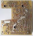
DM501 integrator board
-
Two late DM501s with modified integrator boards
-
DM501 integrator board solder side
-
DM501 rear interface
Components
Some Parts Used in the DM501
| Part | Part Number(s) | Class | Description | Used in |
|---|---|---|---|---|
| 307-1015-00 | 307-1015-00 | Discrete component | resistor network | DM501 |
| Fairchild 3814 | 156-0306-00 | Monolithic integrated circuit | 4½ digit dual-slope DVM controller | 7A13 • 7L13 • 7L18 • DM501 |


