7A29
The Tektronix 7A29 is a 1 GHz single-channel vertical plug-in for 7000-series scopes. It is primarily intended for the 7103 and 7104.
Like with the 7A19, a variable signal delay was available as an option. The 7A29 was designed by John Addis.
There is also a 7A29P, which has digitally programmable gain, intended for the 7000 series digitizers and the 7854 only.
The 7F10 uses the 7A29's amplifier board after the optical/electrical converter.
Key Specifications
| Bandwidth | 1 GHz (in 7104) |
|---|---|
| Input impedance | 50±1 Ω, VSWR <1.2:1 from DC to 1 GHz (10 mV/Div: 1.4:1, Opt.4: 1.5:1) |
| Max. input | max. 10 VRMS or 1 Ws pulses not exceeding 50 V; max. 100 V additional DC component in AC mode |
| Deflection | 10 mV/div to 1 V/div, 1-2-5, ±2%; variable 2.5:1 |
| Channels | Single channel |
| Recommended probes | P6056 (×10), P6057 (×100) |
| Options | Option 4: variable delay (1 ns) |
Links
- Tektronix 7A29 teardown - nice detailed pictures of attenuator internals
- Tek 7A29 @ amplifier.cd including internal pictures
- Tek 7A26 Lab Checkin A special warning about permanent damage @ Zenwizard Studios
Documents Referencing 7A29
| Document | Class | Title | Authors | Year | Links |
|---|---|---|---|---|---|
| Tekscope 1979 V11 N1.pdf | Article | 1 GHz at 1 mV in a General Purpose Plug-in Oscilloscope | Hans Springer | 1979 | 7104 • Hypcon • SHFIII • 7A29 • 7B10 • 7B15 |
| RISOM2873.pdf | Article | Improvement of the Bandwidth of the Transient Digitizers in the LIDAR Thomson Scattering Diagnostic on JET | Erik Kristensen | 1990 | 7912AD • 7A29 • 7704A • 7S12 • S-6 • S-52 |
Patents that may apply to 7A29
| Page | Title | Inventors | Filing date | Grant date | Links |
|---|---|---|---|---|---|
| Patent US 4132958A | Feedbeside correction circuit for an amplifier | John Addis • Bruce Hofer | 1977-10-31 | 1979-01-02 | 7104 • 7A29 • 7F10 |
Internals
The 7A29 employs a number of Tek-made custom Hypcon-packaged hybrids, the 155-0180-00 fast input protection, 155-0181-00 input amplifier and 155-0175-00 trigger amplifier (2 ×). It also uses the 155-0076-00 input protection IC initially developed for the 485.
It uses a "feed-beside" scheme implemented with standard low-frequency operational amplifiers to compensate for low-frequency anomalies in the frequency response that are attributed to transistor heating (see Patent US 4132958A).
The input connector is a special Tek-made part that is exactly 50 Ω. Typical BNC connectors are around 52 Ω.
The 7A29 does not use the ±50 V supplies provided by the mainframe.
Although the 7A29 has a VARIABLE gain control, this control has the undesirable side-effect of also affecting bandwidth. See bandwidth versus VARIABLE gain plot below.
Repair issues
The input attenuator connected to the Volts/Div switch is very delicate. Three plastic levers actuate the ×2, ×10, and ×5 attenuator switches. Small metal rollers are clipped into the plastic levers and ride on cams. The plastic clips did not age well and have become very brittle. Combined with lack of lubrication on the metal rollers this often leads to broken plastic clips and missing rollers. Do not operate a stiff Volts/Div switch and lubricate rollers before use!
Prices
| Year | 1980 | 1985 | 1990 |
|---|---|---|---|
| Catalog price | $1,895 (Opt.04 +$350) | $2,855 | $3,775 (Opt.04 +$535) |
| In 2023 Dollars | $7,100 (Opt.04 +$1,300) | $8,100 | $8,900 (Opt.04 +1,300) |
Pictures
-
7A29 (no opt.) front
-
7A29 Opt.4 front
-
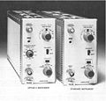
photo of 7A29 from manual (standard and option 4 units)
-
7A29 with GR-874 factory mod
-
7A29 bandwidth versus variable gain
Internal
-
7A29 (no opt.), left side (fixed delay line)
-
7A29 Opt.4, left view (variable delay line enclosure above PCB)
-
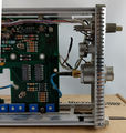
7A29, right side
-
7A29 input protection relay
-
7A29 input protection relay lever
-
7A29 backplane connector (stripline signal path)
-
7A29 amplifiers
-
7A29, right side, rear
-
7A29, right side, front
-
7A29 with GR-874 factory mod
-
7A29 with GR-874 factory mod
Schematics
-
input amplifier schematic
-
output amplifier schematic


