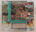
7L5: Difference between revisions
No edit summary |
No edit summary |
||
| (35 intermediate revisions by 5 users not shown) | |||
| Line 1: | Line 1: | ||
{{Plugin Sidebar | {{Plugin Sidebar | ||
|manufacturer=Tektronix | |||
summary=5 MHz Spectrum Analyzer| | |series=7000-series scopes | ||
image=Tek 7l5 1.jpg| | |type=7L5 | ||
caption=Tektronix 7L5 | | |summary=5 MHz Spectrum Analyzer | ||
introduced=1976 | | |image=Tek 7l5 1.jpg | ||
discontinued=1989 | | |caption=Tektronix 7L5 | ||
|introduced=1976 | |||
|discontinued=1989 | |||
* [ | |designers=Fendall Winston;Craig Bryant;Steve Morton;Bill Benedict;Don Kirkpatrick;Steve Skidmore;Carlos Beeck;Morris Engelson | ||
* [http:// | |manuals= | ||
* [[Media:070-1734-00.pdf|Tektronix 7L5 Operators Manual -00]] (OCR) | |||
* [http://pcbunn.cacr.caltech.edu/jjb/Tektronix/7L5/Tek_7L5_Options.pdf Tektronix 7L5 Options Manual (PDF) | * [[Media:070-1734-01.pdf|Tektronix 7L5 Operators Manual -01]] (OCR) | ||
* [[Media:070-2184-01.pdf|Tektronix 7L5 Service Manual]] (OCR) | |||
* [[Media:070-2155-03.pdf|Tektronix 7L5 Options Manual]] (OCR) <small>(1982 version; options 32 and 33 only covered as 1983 addendum page)</small> | |||
<small> | |||
'''Calibration''' | |||
* [[Media:Tek 7L5 factory cal september 1975.pdf|Tektronix 7L5 Factory Calibration Procedure]] | |||
'''Application Notes''' | |||
* [[Media:AX-3406-1.pdf|EMI Applications using the Spectrum Analyzer]] | |||
* [[Media:AX-3535.pdf|Crystal Device Measurements using the Spectrum Analyzer]] | |||
<small> | |||
'''Alternate copies''' | |||
* [https://bama.edebris.com/download/tek/7l5/7l5-spectrum-analyzer.pdf Tektronix 7L5 Manual] @ BAMA | |||
* [http://pcbunn.cithep.caltech.edu/jjb/Tektronix/7L5/7l5-spectrum-analyzer.pdf Military PL-1391/U manual] (Text) | |||
* [http://pcbunn.cacr.caltech.edu/jjb/Tektronix/7L5/Tek_7L5_Options.pdf Tektronix 7L5 Options Manual] (PDF) | |||
</small> | |||
}} | }} | ||
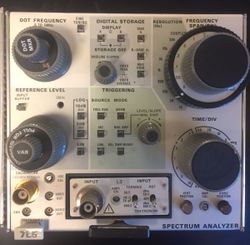
The '''Tektronix 7L5''' is a low frequency (10 Hz – 5 MHz) spectrum analyzer plug-in for [[7000-series scopes]]. | |||
It has built-in digital storage, so it will work fine in non-storage mainframes such as the large-screen [[7603]]. | |||
It also features digital scale and marker level/frequency (6 digits) readout, and a "max hold" function. | |||
According to the 070-2184-01 manual, instruments with a serial number below Β070000 are missing the ''B − (Save A)'' feature and the corresponding button on the front panel. The military version is called PL-1391/U and is also lacking the ''B − (Save A)'' feature. | |||
<blockquote> | |||
Fendall Winston was Project Leader for the 7L5 and along with Craig Bryant and Steve Morton provided much of the electrical design. Bill Benedict and Don Kirkpatrick did the digital circuitry. Steve Skidmore coordinated mechanical design, with Carlos Beeck doing the optoelectronic switch-in-a-knob. Morris Engelson provided overall engineering direction for the program. | |||
</blockquote> | |||
{{BeginSpecs}} | {{BeginSpecs}} | ||
{{Spec|Input frequency | 10 Hz – 5 MHz}} | {{Spec|Input frequency | 10 Hz – 5 MHz}} | ||
{{Spec|Drift | < 5 Hz / | {{Spec|Drift | < 5 Hz/h }} | ||
{{Spec|Resolution bandwidth| 10 Hz – 30 kHz in ×3 / ×10 steps}} | {{Spec|Resolution bandwidth| 10 Hz – 30 kHz in ×3 / ×10 steps}} | ||
{{Spec|Sweep rate | 10 s /Div to 0.1 ms/Div in | {{Spec|Sweep rate | 10 s/Div to 0.1 ms/Div in 1−2−5 sequence plus Auto}} | ||
{{Spec|Residual FM | < 40 Hz<sub>p-p</sub> (< 1 Hz from 50 Hz/Div to 2 kHz/Div)}} | {{Spec|Residual FM | < 40 Hz<sub>p-p</sub> (< 1 Hz from 50 Hz/Div to 2 kHz/Div)}} | ||
{{Spec|Outputs | Horizontal, Video, Calibrator}} | {{Spec|Outputs | Horizontal, Video, Calibrator}} | ||
{{Spec|Input impedance| | {{Spec|Input impedance| | ||
* [[L1]] input module: | * [[L1]] input module: 50 Ω | ||
* [[L2]] input module: | * [[L2]] input module: 75 Ω | ||
* [[L3]] input module: | * [[L3]] input module: 50 Ω, 600 Ω or 1 MΩ selectable (75 Ω, 600 Ω or 1 MΩ for the L3-1) | ||
}} | }} | ||
{{Spec|Log Sweep Option| 250 Hz to 222.25 kHz by digitally combining three decade sweeps (250 Hz—2.25 kHz, 2.25 kHz—22.25 kHz, 22.25 kHz—222.25 kHz), 2.5 s sweep time }} | |||
{{EndSpecs}} | {{EndSpecs}} | ||
====Options==== | ====Options==== | ||
<small> | |||
:{| border="1" cellspacing="0" | | :{| border="1" cellspacing="0" | | ||
|- | |- | ||
| Line 52: | Line 76: | ||
|- | |- | ||
|} | |} | ||
</small> | |||
==Links== | ==Links== | ||
* [ | * [https://www.amplifier.cd/Test_Equipment/Tektronix/Tektronix_7000_series_special/7L5.html 7L5 page @ amplifier.cd] with internal photos | ||
* [https://www.youtube.com/watch?v=tm4Y5Tv1huk 7L5 in operation @ youtube] | * [https://www.youtube.com/watch?v=tm4Y5Tv1huk 7L5 in operation @ youtube] | ||
* [[L1-GC]] | |||
{{Documents|Link=7L5}} | |||
In [[Media:TekWeek (partial) October 10, 1975.pdf|TekWeek 10 Oct 1975]], [[Thor Hallen]] says | |||
<blockquote> | |||
''What is the Communications division doing to improve the reliability and field failure rates of high technology instruments such as the 7L5, 7L12 and 7L13 spectrumanalyzers?'' | |||
Glad you asked! High technology instruments such as the spectrum analyzers you mentioned pose enormous problems in maintaining Tektronix standards for high reliability. | |||
Let’s consider the 7L5 for example. The 7L5 is the newest and most dense analyzer to date. It has approximately 2200 electrical parts packed into a two wide plug-in. | |||
(The 7L12 and 7L13 are slightly less dense.) With such a high parts population, a 0.5%/year failure rate for individual parts would be disastrous. | |||
In order to deliver better reliability, extraordinary steps are being implemented within the manufacturing area. | |||
All benches have been covered with “pink poly” to make a static-free environment for the sensitive Metal Oxide Semiconductor (MOS) circuits of the 7L5. | |||
Assemblers and technicians are being trained in static handling of these devices. | |||
The most embarrassing reliability problem that can occur is when the customer has an instrument failure within the first few hours of operation. | |||
To prevent this, the 7L5 goes through an extensive 7 day cycled burn-in. Each day the instrument is checked for electrical performance. | |||
Any failures are repaired and the burn-in is continued until the instrument has completed the 7 days. | |||
Any failures in the last two days will cause the burn-in to continue until the instrument displays two consecutive days without a failure. | |||
Along with burn-in and special handling, extensive effort is given to analysis of field and plant failures for reliability problems. | |||
In answer to your question, we have only discussed the 7L5, but the [[7L12]] and [[7L13]] receive similar treatment. | |||
There is no final solution to improved reliability. As instruments increase in complexity and reliability, challenge increases proportionately. | |||
</blockquote> | |||
==Prices== | |||
{| class="wikitable" | |||
|- | |||
! Year | |||
! 1976 | |||
! 1980 | |||
! 1988 | |||
|- | |||
! Catalog price | |||
| align="right" | $4,500 | |||
| align="right" | $7,075 | |||
| align="right" | $12,500 | |||
|- | |||
! In 2023 Dollars | |||
| align="right" | $24,300 | |||
| align="right" | $26,400 | |||
| align="right" | $32,400 | |||
|- | |||
|} | |||
According to an [[Media:Tek Schottky Diodes Memo rot.pdf|internal memo]], in 1979 annual sales were estimated at 454 units. | |||
==Pictures== | ==Pictures== | ||
| Line 64: | Line 135: | ||
7L5-opt25-cal.jpg | 7L5 Opt. 25 | 7L5-opt25-cal.jpg | 7L5 Opt. 25 | ||
7844-3.jpg | 7L5 in [[7844]] | 7844-3.jpg | 7L5 in [[7844]] | ||
7L5 no B-saveA.jpg | 7L5 Opt. 25 without B - (Save A) | |||
Tek 7l5 in 7633.jpg | Tek 7l5 in 7633.jpg | ||
Tek_7l5_front_panel.jpg|Front Panel of 7L5 | |||
Tek_7l5_front_panel_back.jpg|Back side of 7L5 front panel | |||
Tek_7l5_complete_if_assembly_01.jpg|Complete IF Assembly of 7L5 | |||
Tek_7l5_complete_if_assembly_02.jpg|Complete IF Assembly of 7L5 | |||
Tek_7l5_RF_module_front.jpg|RF Module (Vertical Control Board and 1st LO assembly) of 7L5 | |||
Tek_7l5_sweep_front.jpg|Sweep board of 7L5 | |||
Tek_7l5_oscillator_ctrl_front.jpg|7L5 A and B oscillator control board front side | |||
Tek_7l5_oscillator_ctrl_back.jpg|7L5 A and B oscillator control board back side | |||
Tek_7l5_tune_reference_A_front.jpg|Front side of Tune Reference A board | |||
Tek_7l5_tune_reference_A_back.jpg|Back side of Tune Reference A board | |||
Tek_7l5_tune_reference_B_front.jpg|Front side of Tune Reference B board | |||
Tek_7l5_tune_reference_B_back.jpg|Back side of Tune Reference B board | |||
Tek_7l5_A_oscillator_front.jpg|Front side of A oscillator board | |||
Tek_7L5_A_oscillator_back.jpg|Back side of A oscillator board | |||
Tek_7l5_B_oscillator_front.jpg|Front side of B oscillator board | |||
Tek_7l5_B_oscillator_back.jpg|Back side of B oscillator board | |||
Tek_7l5_late_digital_storage_front.jpg|Later revision of 7L5 digital storage and average board - front side | |||
Tek_7l5_late_digital_storage_back.jpg|Later revision of 7L5 digital storage and average board - back side | |||
Tek_7l5_transverse_interface_01.jpg|Tektronix 7L5 Transverse Interface Board | |||
Tek_7l5_transverse_interface_02.jpg|Tektronix 7L5 Transverse Interface Board | |||
Tek_7l5_L3_plugin_top.jpg|Top view of L3 plugin assembly | |||
Tek_7l5_L3_plugin_bottom.jpg|Bottom view of L3 plugin assembly | |||
Tek_7l5_sweep_diagnostics.jpg|7L5 prepared for servicing the sweep and reference boards | |||
</gallery> | </gallery> | ||
| Line 73: | Line 170: | ||
Tek option 25.1 tracking gen right.jpg | Tek option 25.1 tracking gen right.jpg | ||
</gallery> | </gallery> | ||
For internal pictures see the [[7L5/Repairs|repair section]]. | |||
==Components== | |||
{{Parts|7L5}} | |||
[[Category:7000 series combined plugins]] | [[Category:7000 series combined plugins]] | ||
[[Category: | [[Category:7000 series spectrum analyzer plugins]] | ||
Latest revision as of 01:56, 15 March 2024
The Tektronix 7L5 is a low frequency (10 Hz – 5 MHz) spectrum analyzer plug-in for 7000-series scopes. It has built-in digital storage, so it will work fine in non-storage mainframes such as the large-screen 7603. It also features digital scale and marker level/frequency (6 digits) readout, and a "max hold" function.
According to the 070-2184-01 manual, instruments with a serial number below Β070000 are missing the B − (Save A) feature and the corresponding button on the front panel. The military version is called PL-1391/U and is also lacking the B − (Save A) feature.
Fendall Winston was Project Leader for the 7L5 and along with Craig Bryant and Steve Morton provided much of the electrical design. Bill Benedict and Don Kirkpatrick did the digital circuitry. Steve Skidmore coordinated mechanical design, with Carlos Beeck doing the optoelectronic switch-in-a-knob. Morris Engelson provided overall engineering direction for the program.
Key Specifications
| Input frequency | 10 Hz – 5 MHz |
|---|---|
| Drift | < 5 Hz/h |
| Resolution bandwidth | 10 Hz – 30 kHz in ×3 / ×10 steps |
| Sweep rate | 10 s/Div to 0.1 ms/Div in 1−2−5 sequence plus Auto |
| Residual FM | < 40 Hzp-p (< 1 Hz from 50 Hz/Div to 2 kHz/Div) |
| Outputs | Horizontal, Video, Calibrator |
| Input impedance | |
| Log Sweep Option | 250 Hz to 222.25 kHz by digitally combining three decade sweeps (250 Hz—2.25 kHz, 2.25 kHz—22.25 kHz, 22.25 kHz—222.25 kHz), 2.5 s sweep time |
Options
No. Log sweep display Tracking generator LED Readout 21 • 25 • 28 • 30 • • 31 • • 32 • • 33 • • •
Links
- 7L5 page @ amplifier.cd with internal photos
- 7L5 in operation @ youtube
- L1-GC
Documents Referencing 7L5
| Document | Class | Title | Authors | Year | Links |
|---|---|---|---|---|---|
| Tekscope 1975 V7 N3.pdf | Article | A 5 MHz Digitally-Controlled Spectrum Analyzer | 1975 | 7L5 | |
| TekWeek (partial) October 10, 1975.pdf | Article | Spectrum analyzers require high technology | Thor Hallen • Dave Friedley | 1975 | Spectrum Analyzers • Pentrix • 7L5 • 5L4 • 7L12 • 7L13 • 1401 • 491 • 1405 • 1502 • 1503 |
| AX-3535.pdf | Application Note | Crystal Device Measurements Using the Spectrum Analyzer | Morris Engelson | 1977 | 7L5 |
| Tekscope 1977 V9 N3.pdf | Article | Digital Storage for a Microwave Spectrum Analyzer | Dennis Smith • Don Kirkpatrick | 1977 | 7L18 • 7L5 • 155-0157-00 • 155-0158-00 |
| Tekscope 1977 V9 N2.pdf | Article | Measuring Harmonic Distortion with a Spectrum Analyzer | Ken Matheson | 1977 | FG504 • 7L5 • 5L4N |
| Tekscope 1978 V10 N3.pdf | Article | Spectrum Analyzer Applications in Baseband Measurements | Morris Engelson | 1978 | 7L5 • 013-0182-00 |
| AX-3406-1.pdf | Application Note | EMI Applications Using the Spectrum Analyzer | Morris Engelson | 1979 | 7L5 |
In TekWeek 10 Oct 1975, Thor Hallen says
What is the Communications division doing to improve the reliability and field failure rates of high technology instruments such as the 7L5, 7L12 and 7L13 spectrumanalyzers?
Glad you asked! High technology instruments such as the spectrum analyzers you mentioned pose enormous problems in maintaining Tektronix standards for high reliability. Let’s consider the 7L5 for example. The 7L5 is the newest and most dense analyzer to date. It has approximately 2200 electrical parts packed into a two wide plug-in. (The 7L12 and 7L13 are slightly less dense.) With such a high parts population, a 0.5%/year failure rate for individual parts would be disastrous.
In order to deliver better reliability, extraordinary steps are being implemented within the manufacturing area. All benches have been covered with “pink poly” to make a static-free environment for the sensitive Metal Oxide Semiconductor (MOS) circuits of the 7L5. Assemblers and technicians are being trained in static handling of these devices.
The most embarrassing reliability problem that can occur is when the customer has an instrument failure within the first few hours of operation. To prevent this, the 7L5 goes through an extensive 7 day cycled burn-in. Each day the instrument is checked for electrical performance. Any failures are repaired and the burn-in is continued until the instrument has completed the 7 days. Any failures in the last two days will cause the burn-in to continue until the instrument displays two consecutive days without a failure.
Along with burn-in and special handling, extensive effort is given to analysis of field and plant failures for reliability problems.
In answer to your question, we have only discussed the 7L5, but the 7L12 and 7L13 receive similar treatment. There is no final solution to improved reliability. As instruments increase in complexity and reliability, challenge increases proportionately.
Prices
| Year | 1976 | 1980 | 1988 |
|---|---|---|---|
| Catalog price | $4,500 | $7,075 | $12,500 |
| In 2023 Dollars | $24,300 | $26,400 | $32,400 |
According to an internal memo, in 1979 annual sales were estimated at 454 units.
Pictures
-
-
7L5 Opt. 33 in 7633 mainframe
-
7L5 Opt. 32
-
7L5 Opt. 25
-
7L5 in 7844
-
7L5 Opt. 25 without B - (Save A)
-
-
Front Panel of 7L5
-
Back side of 7L5 front panel
-
Complete IF Assembly of 7L5
-
Complete IF Assembly of 7L5
-
RF Module (Vertical Control Board and 1st LO assembly) of 7L5
-
Sweep board of 7L5
-
7L5 A and B oscillator control board front side
-
7L5 A and B oscillator control board back side
-
Front side of Tune Reference A board
-
Back side of Tune Reference A board
-
Front side of Tune Reference B board
-
Back side of Tune Reference B board
-
Front side of A oscillator board
-
Back side of A oscillator board
-
Front side of B oscillator board
-
Back side of B oscillator board
-
Later revision of 7L5 digital storage and average board - front side
-
Later revision of 7L5 digital storage and average board - back side
-
Tektronix 7L5 Transverse Interface Board
-
Tektronix 7L5 Transverse Interface Board
-
Top view of L3 plugin assembly
-
Bottom view of L3 plugin assembly
-
7L5 prepared for servicing the sweep and reference boards
7L5 Opt.25 tracking generator plug-in
For internal pictures see the repair section.
Components
Some Parts Used in the 7L5
| Part | Part Number(s) | Class | Description | Used in |
|---|---|---|---|---|
| 151-0261-00 | 151-0261-00 | Discrete component | dual PNP transistor | AM501 • AM502 • CG5001 • CG551AP • FG501 • FG502 • FG503 • OF150 • OF151 • OF152 • OF235 • OS261 • RM502A • R1140 • R5030 • R5031 • R7912 • 067-0679-00 • 067-0807-00 • 1101 • 1140A • 1141 • 1142 • 1350 • 145 • 1450 • 1480 • 1481 • 1482 • 1485 • 1501 • 1801 • 1900 • 1910 • 1980 • 213 • 26A1 • 26A2 • 2620 • 285 • 3A9 • 3A10 • 3S1 • 3S2 • 3S5 • 3S6 • 432 • 434 • 4501 • 454 • 4601 • 4602 • 4610 • 4612 • 4620 • 4632 • 4634 • 4701 • 475 • 492 • 492A • 492AP • 494 • 494P • 496 • 496P • 5A13N • 5A20N • 5A21N • 5A22N • 5A26 • 5L4N • 502A • 5030 • 5031 • 576 • 690SR • 7A22 • 7A29 • 7B51 • 7B71 • 7J20 • 7L5 • 7S11 • 7S12 • 7912AD |
| 155-0014-01 | 155-0014-00 • 155-0014-01 | Monolithic integrated circuit | A/D converter | 7000 series readout system • 7854 • 7934 • 7J20 • 7L5 • P7001 |
| 155-0035-00 | 155-0035-00 • 155-0116-00 | Monolithic integrated circuit | quad op-amp | 3110 • 3S7 • 3T7 • 492 • 492A • 492AP • 492P • 494 • 494P • 496 • 496P • 4010 • 4011 • 4012 • 4013 • 7L5 • 7L12 • 7L13 • 7L14 • 7L18 • 7S11 • 7T11 • 7S12 • S-6 • 1461 • 4602 • P7001 • 613 • 653 |
| 155-0056-00 | 155-0056-00 • 155-0056-01 | Monolithic integrated circuit | sweep control | 26G1 • 26G2 • 26G3 • 314 • 4701 • 5B10N • 5B12N • 5S14N • 7L5 • 7L12 • 7L13 • 7L14 • 7L18 • 7S14 • 5S14N • RG501 • Telequipment D63 • Telequipment DM63 |
| 155-0108-00 | 155-0108-00 | Monolithic integrated circuit | operational amplifier | 7L5 |
| 155-0110-00 | 155-0110-00 | Monolithic integrated circuit | custom legend generator | 7L5 |
| 155-0117-00 | 155-0117-00 | Monolithic integrated circuit | readout control | 7L5 |
| 155-0118-00 | 155-0118-00 | Monolithic integrated circuit | vertical control | 7L5 |
| 155-0157-00 | 155-0157-00 | Monolithic integrated circuit | digital storage vertical control | 7L5 • 7L14 • 7L18 • 491 • 492 • 492A • 492BP • 492PGM • 494 • 494A • 495 • 496 • 497P |
| 155-0158-00 | 155-0158-00 | Monolithic integrated circuit | digital storage horizontal control | 7L5 • 7L14 • 7L18 • 491 • 492 • 492A • 492BP • 492PGM • 494 • 494A • 495 • 496 • 497P |
| 155-0198-00 | 155-0198-00 | Monolithic integrated circuit | readout control | 7L5 |
| 155-0199-00 | 155-0199-00 | Monolithic integrated circuit | vertical control | 7L5 |
| VTL2C4 | 307-0476-00 | Discrete component | LED-LDR optocoupler | 7L5 |
