PG505: Difference between revisions
No edit summary |
No edit summary |
||
| (26 intermediate revisions by 3 users not shown) | |||
| Line 1: | Line 1: | ||
{{TM500 | mfg=Tektronix | type=PG505 | function= | {{TM500 | ||
manuals= | |mfg=Tektronix | ||
* [ | |type=PG505 | ||
|function=100 kHz, 80 V pulse generator | |||
|class=pulse generator | |||
|image=Tek_pg505_front1.jpg | |||
|introduced=1974 | |||
|discontinued=1983 | |||
|manuals= | |||
* [[Media:070-1583-01.pdf|Tektronix PG505 Manual 070-1583-01]] (OCR) '''''See errata''''' | |||
}} | }} | ||
The output section is isolated from chassis ground and can float up to ±200 V. | |||
[[ | {{BeginSpecs}} | ||
[[ | {{Spec | Period | 10 μs to 100 ms in decade steps, one custom position (≥10 μs), variable control ×1 to ×10 }} | ||
{{Spec | Pulse width | 5 μs to 50 ms in decade steps, one custom position (≥5 μs), variable control ×1 to ×10 }} | |||
{{Spec | Rise/Fall times | 1 μs to 1 ms in decade steps, variable control ×1 to ×20 }} | |||
{{Spec | Amplitude | ±4 to min. ±80 V from a 4 kΩ source, floating up to ±200 V to chassis ground (with grounding strap removed, see note) }} | |||
{{Spec | Duty cycle | min. pulse width to 99% }} | |||
{{Spec | Input | Delay/Duration, 0 – 10 V into ≥10 kΩ }} | |||
{{Spec | Gate input | +5 V to inhibit free-running rate generator (rear interface only) }} | |||
{{Spec | Trigger output | min. +4 V into 10 kΩ / 3 V into 600 Ω, same duration as output }} | |||
{{EndSpecs}} | |||
==Links== | |||
{{Documents|Link=PG505}} | |||
{{PatentLinks|PG505}} | |||
===Notes=== | |||
* '''''Manual errata:''' In manual 070-1583-01, Fig. 4.3 Output Delay Range Check (p. 4-5), the PG 505 connections are drawn correctly but the connector labels are swapped – the left connector fed from the FG501A via the BNC "T" is the Delay/Duration input, not the output. In Table 5-2, Rear Connector Pin Assignments (p. 5-8), [[TM500 Series plug-in interface|pin B7]] is incorrectly labeled –33.5 V, it is the NPN pass transistor's collector.'' | |||
* The PG505 is shipped with the output connector ground connected to chassis ground through a removable ground strap. This must be cut/removed to float the output, in which case output common remains grounded through a 100 kΩ resistor (R545). The manual says this resistor may be removed too, but doing so will cause unspecified "degradation of performance". | |||
==Operation== | |||
The main controls are a pair of concentric switches for pulse period and pulse duration, with the latter mechanically limited to prevent the duration range to be set higher than the period range. | |||
When period and duration switches are in the same position and the variable controls set ×1 (ccw) the output runs at 50% duty cycle. | |||
In the leftmost position of the duration switch, the output is locked in its "on" state so that the amplitude can be set conveniently with a DC voltmeter attached to the output. | |||
The second-rightmost position of either switch is reserved for a custom period or duration that is defined by an optional, customer-installed capacitor for each. | |||
Two pairs of test point lugs on the circuit board (near the cam switch cover) are provided to install these capacitors. | |||
In the rightmost position of the period switch ("OUTPUT DELAYED"), the rate generator is disabled. | |||
The signal on the Delay/Ext Duration input, assumed to be a positive-going 10 V ramp, is compared to the setting of the Output Delay potentiometer. | |||
When the ramp reaches the threshold, an output pulse of the set duration is triggered. | |||
When the duration switch is put in the rightmost position as well (which mechanically forces the period switch to the same), both the rate and duration generator circuits are disabled. | |||
In this "EXT DURATION" mode, the output simply follows the Delay/Ext Duration input as compared to the threshold set by the variable delay potentiometer (0−10 V). | |||
==Rear Interface== | |||
* B27: Trig Out (9A/9B ground) | |||
* B24: Ext Delay In (9A/9B ground) | |||
* B24: Ext Gate In (9A/9B ground) | |||
Family key: Signal source (between pins 23 and 34) | |||
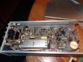
==Internals== | |||
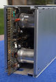
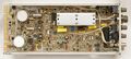
The rate generator (free-running, discrete) and duration generator (a Fairchild 9601 TTL monoflop) are operating on the chassis-referenced power rails. | |||
A small toroidal transformer couples the generated pulse to the output section in the form of differentiated positive and negative pulses. | |||
On the floating side, a Schmitt trigger section restores the square pulse, which steers the output of a pair of current sources via a diode bridge into one of four switch-selected capacitors to create the variable rise and fall time. | |||
The output amplifier has a dual FET ([[2N3958]]) source follower input. | |||
Two half-wave rectifiers, fed by the series-connected floating 25 V mainframe transformer windings, produce an unregulated floating supply of about ±65 V, from which regulated +48 V, +20 V, –10 V, –10 V, –20 V, and –48 V are derived. | |||
Depending on the selected output polarity, either +48 V or –48 V (less an adjustable component) is referenced to output ground. The push-pull output stage therefore has about 96 V supply available. | |||
The output is short-circuit protected by a fixed 4 kΩ series resistor. | |||
==Prices== | |||
{| class="wikitable sortable" | |||
|- | |||
! Year | |||
! 1974 | |||
! 1975 | |||
! 1980 | |||
! 1982 | |||
|- | |||
! Catalog Price | |||
| align="right" | $265 | |||
| align="right" | $295 | |||
| align="right" | $550 | |||
| align="right" | $840 | |||
|- | |||
! In 2024 Dollars | |||
| align="right" | $1,700 | |||
| align="right" | $1,700 | |||
| align="right" | $2,100 | |||
| align="right" | $2,700 | |||
|} | |||
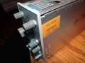
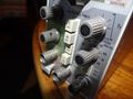
==Pictures== | |||
<gallery> | |||
Tek pg505 front1.jpg | |||
Tek pg505 front2.jpg | |||
Tek pg505 rear.jpg | |||
Tek pg505 top.jpg | |||
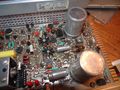
Tek PG505 circuit_board.jpg | | |||
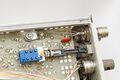
Tek PG505 output.jpg | Output connector – note ground strap (to chassis lug) | |||
Tek pg505 1.jpg | |||
Tek pg505 2.jpg | |||
Tek pg505 3.jpg | |||
Tek pg505 4.jpg | |||
Tek pg505 5.jpg | |||
Tek pg505 6.jpg | |||
Tek pg505 7.jpg | |||
</gallery> | |||
'''Examples''' | |||
<gallery> | |||
Tek PG505 Ext Duration 1 kHz.png | External Duration mode. 1 kHz Triangle input on CH3, Trig Out on CH2, Output on CH1 | |||
Tek PG505 Ext Duration 0.1 and 10 Hz.png | Same as above, with 0.1 and 10 Hz input | |||
</gallery> | |||
==Components== | |||
{{Parts|PG505}} | |||
Latest revision as of 01:55, 6 October 2024

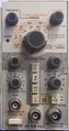
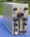
The Tektronix PG505 is a 100 kHz, 80 V pulse generator plug-in for the TM500 system.
The output section is isolated from chassis ground and can float up to ±200 V.
Key Specifications
| Period | 10 μs to 100 ms in decade steps, one custom position (≥10 μs), variable control ×1 to ×10 |
|---|---|
| Pulse width | 5 μs to 50 ms in decade steps, one custom position (≥5 μs), variable control ×1 to ×10 |
| Rise/Fall times | 1 μs to 1 ms in decade steps, variable control ×1 to ×20 |
| Amplitude | ±4 to min. ±80 V from a 4 kΩ source, floating up to ±200 V to chassis ground (with grounding strap removed, see note) |
| Duty cycle | min. pulse width to 99% |
| Input | Delay/Duration, 0 – 10 V into ≥10 kΩ |
| Gate input | +5 V to inhibit free-running rate generator (rear interface only) |
| Trigger output | min. +4 V into 10 kΩ / 3 V into 600 Ω, same duration as output |
Links
Documents Referencing PG505
Patents that may apply to PG505
| Page | Title | Inventors | Filing date | Grant date | Links |
|---|---|---|---|---|---|
| Patent US 3562464A | Cam actuated switch having movable and fixed contacts on circuit board | Howard Vollum • Willem H Verhoef • Tony Sprando | 1968-10-07 | 1971-02-09 | Cam switches • 2101 • 2701 • 2703 • 432 • 434 • 465 • 475 • 5A38 • 5A45 • 7A15 • 7A16A • 7A18 • 7A19 • 7A24 • 7A26 • 7B10 • 7B15 • 7B50 • 7B51 • 7B52 • 7B53A • 7B50A • 7B70 • 7B71 • 7B80 • 7B85 • 7B87 • 7B92 • 7B92A • 7D01 • 7D12 • 7D15 • 7J20 • 7S12 • 7T11 • 7T11A • AF501 • AM502 • AM503 • DC502 • DC503 • DC504 • DC505 • DM501 • DM502 • FG501 • FG501A • FG502 • FG503 • FG504 • FG507 • PG501 • PG502 • PG505 • PG506 • PG506A • PG508 • TG501 • SC502 • SC503 • SC504 |
Notes
- Manual errata: In manual 070-1583-01, Fig. 4.3 Output Delay Range Check (p. 4-5), the PG 505 connections are drawn correctly but the connector labels are swapped – the left connector fed from the FG501A via the BNC "T" is the Delay/Duration input, not the output. In Table 5-2, Rear Connector Pin Assignments (p. 5-8), pin B7 is incorrectly labeled –33.5 V, it is the NPN pass transistor's collector.
- The PG505 is shipped with the output connector ground connected to chassis ground through a removable ground strap. This must be cut/removed to float the output, in which case output common remains grounded through a 100 kΩ resistor (R545). The manual says this resistor may be removed too, but doing so will cause unspecified "degradation of performance".
Operation
The main controls are a pair of concentric switches for pulse period and pulse duration, with the latter mechanically limited to prevent the duration range to be set higher than the period range. When period and duration switches are in the same position and the variable controls set ×1 (ccw) the output runs at 50% duty cycle.
In the leftmost position of the duration switch, the output is locked in its "on" state so that the amplitude can be set conveniently with a DC voltmeter attached to the output.
The second-rightmost position of either switch is reserved for a custom period or duration that is defined by an optional, customer-installed capacitor for each. Two pairs of test point lugs on the circuit board (near the cam switch cover) are provided to install these capacitors.
In the rightmost position of the period switch ("OUTPUT DELAYED"), the rate generator is disabled. The signal on the Delay/Ext Duration input, assumed to be a positive-going 10 V ramp, is compared to the setting of the Output Delay potentiometer. When the ramp reaches the threshold, an output pulse of the set duration is triggered.
When the duration switch is put in the rightmost position as well (which mechanically forces the period switch to the same), both the rate and duration generator circuits are disabled. In this "EXT DURATION" mode, the output simply follows the Delay/Ext Duration input as compared to the threshold set by the variable delay potentiometer (0−10 V).
Rear Interface
- B27: Trig Out (9A/9B ground)
- B24: Ext Delay In (9A/9B ground)
- B24: Ext Gate In (9A/9B ground)
Family key: Signal source (between pins 23 and 34)
Internals
The rate generator (free-running, discrete) and duration generator (a Fairchild 9601 TTL monoflop) are operating on the chassis-referenced power rails. A small toroidal transformer couples the generated pulse to the output section in the form of differentiated positive and negative pulses.
On the floating side, a Schmitt trigger section restores the square pulse, which steers the output of a pair of current sources via a diode bridge into one of four switch-selected capacitors to create the variable rise and fall time. The output amplifier has a dual FET (2N3958) source follower input.
Two half-wave rectifiers, fed by the series-connected floating 25 V mainframe transformer windings, produce an unregulated floating supply of about ±65 V, from which regulated +48 V, +20 V, –10 V, –10 V, –20 V, and –48 V are derived. Depending on the selected output polarity, either +48 V or –48 V (less an adjustable component) is referenced to output ground. The push-pull output stage therefore has about 96 V supply available.
The output is short-circuit protected by a fixed 4 kΩ series resistor.
Prices
| Year | 1974 | 1975 | 1980 | 1982 |
|---|---|---|---|---|
| Catalog Price | $265 | $295 | $550 | $840 |
| In 2024 Dollars | $1,700 | $1,700 | $2,100 | $2,700 |
Pictures
-
-
-
-

-
-
Output connector – note ground strap (to chassis lug)
-

-
-
-

-
-
-


Examples
-

External Duration mode. 1 kHz Triangle input on CH3, Trig Out on CH2, Output on CH1
-

Same as above, with 0.1 and 10 Hz input


Components
Some Parts Used in the PG505
| Part | Part Number(s) | Class | Description | Used in |
|---|---|---|---|---|
| 2N3958 | 151-1054-00 • 151-1054-01 • 151-1054-02 | Discrete component | dual n-channel JFET | FG503 • MR501 • M3 • PG505 • SC501 • SC502 • SC503 • SG502 • 1450 • 1501 • 1502 • 1503 • 221 • 5A23N • 5CT1N • 577 • 603 • 603A • 604 • 604A • 605 • 606 • 606A • 606B • 607 • 607A • 620 • 624 • 7CT1N • 7D15 • 7D20 • 851 |