576: Difference between revisions
mNo edit summary |
No edit summary |
||
| (36 intermediate revisions by 6 users not shown) | |||
| Line 1: | Line 1: | ||
{{ | {{Instrument Sidebar | ||
|manufacturer=Tektronix | |||
summary=Curve tracer | | |class=Curve Tracer | ||
image=576_front_1000.jpg | | |model=576 | ||
caption=Tektronix 576 Curve tracer with | |summary=Curve tracer | ||
introduced=1969 | | |image=576_front_1000.jpg | ||
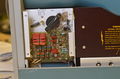
discontinued=1990 | | |caption=Tektronix 576 Curve tracer with standard test fixture | ||
manuals= | |introduced=1969 | ||
|discontinued=1990 | |||
|designers=Jim Knapton; | |||
|manuals= | |||
* [[Media:070-0905-01.pdf|Tektronix 576 Manual, April 1988]] | * [[Media:070-0905-01.pdf|Tektronix 576 Manual, April 1988]] | ||
<!--* [http://w140.com/mmm/tek-576.pdf Tektronix 576 Manual ( | <!-- * [http://w140.com/mmm/tek-576.pdf Tektronix 576 Manual (unfragmented schematics)] --> | ||
<!--* [http://w140.com/tek_576.pdf Tektronix 576 Manual ( | <!--* [http://w140.com/tek_576.pdf Tektronix 576 Manual (OCR, fragmented schematics) --> | ||
* [[Media:Tek 576 dc reference source.pdf|DC Reference Source from 576 | <!--* [[Media:Tek 576 dc reference source.pdf|DC Reference Source from 576]]--> | ||
* [[Media:Tek 576 fcp no ocr.pdf|Tektronix 576 Factory Calibration Procedure May 1969 | * [[Media:Tek 576 fcp no ocr.pdf|Tektronix 576 Factory Calibration Procedure May 1969]] | ||
* [[Media:Tek 576 factory calibration procedure dec 1969.pdf|Tektronix 576 Factory Calibration Procedure December 1969 | * [[Media:Tek 576 factory calibration procedure dec 1969.pdf|Tektronix 576 Factory Calibration Procedure December 1969]] | ||
* [[Media:48w-5764.pdf|Feature Comparison of Tek Curve Tracers with HP 4145A | * [[Media:48w-5764.pdf|Feature Comparison of Tek Curve Tracers with HP 4145A]] | ||
* [[Media:070-1207-00.pdf|Tektronix 576 Adjustment and Performance Check Procedure]] | * [[Media:070-1207-00.pdf|Tektronix 576 Adjustment and Performance Check Procedure]] | ||
* [[Media:070-0970-01.pdf|Tektronix 576 Test Set-up Chart]] | |||
}} | }} | ||
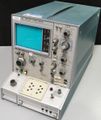
The '''Tektronix 576''' is a curve tracer introduced in 1969 | The '''Tektronix 576''' is a curve tracer [[introduced in 1969]]. | ||
It was designed by [[Jim Knapton]]. | |||
It uses plug-in fixture modules such as the [[172]] and [[176]]. | It uses plug-in fixture modules such as the [[172]] and [[176]]. | ||
Unlike the [[570]], [[575]] and [[7CT1N]], the 576 (and also the [[577]]) provides an AC collector sweep mode. | Unlike the [[570]], [[575]] and [[7CT1N]], the 576 (and also the [[577]]) provides an AC collector sweep mode. | ||
The 576 was the first product to use Tek-made ICs. | |||
The 576's display includes readout of current, voltage, Beta, and gm. | |||
The circuitry for calculating the scales based on the switch positions | |||
was designed by [[Mike Metcalf]] and implemented in custom ICs, e.g., [[155-0005-00]]. | |||
{{BeginSpecs}} | {{BeginSpecs}} | ||
{{Spec | Collector Sweep Ranges | | |||
{| | * 15 V / 10 A | ||
* 75 V / 2 A | |||
* 350V / 0.5 A | |||
* 1500 V / 0.1 A}} | |||
{{Spec | Collector Current Display | 0.1 μA/div to 2 A/div, 1−2−5 }} | |||
{{Spec | Emitter Current Display | 0.1 nA/div to 2 mA/div, 1−2−5 }} | |||
{{Spec | Collector Voltage Display| 5 mV/div to 200 V/div, 1−2−5}} | |||
{{Spec | Base Voltage Display | 5 mV/div to 2 V/div, 1−2−5}} | |||
{{Spec | Base Current Steps | 200 mA to 50 nA, 1−2−5}} | |||
{{Spec | Gate Voltage Steps | 50 mV to 2 V, 1−2−5}} | |||
{{EndSpecs}} | |||
| | |||
| | |||
| | |||
| | |||
| | |||
| | |||
| | |||
| | |||
Note that these specifications are for the [[576 Standard Test Fixture]]. | |||
See [[576 Detailed Specifications]] for more data. | |||
=== | ==Links== | ||
* [[Curve Tracer Adapters]] | |||
* [https://lazyelectrons.wordpress.com/2018/06/12/tektronix-576-curve-tracer-repair-restore Lazy Electrons 576 Restoration Page] | |||
* [http://www.jacmusic.com/Tube-testers/TEK-576/Tek-576-1-General-Part.html Tektronix 576 Curve Tracer System page at JAC Music (Includes a restoration article)] | |||
* [http://www.amplifier.cd/Test_Equipment/Tektronix/Tektronix_other/576.html Tek 576 @ amplifier.cd] (including repair report, mostly in German) | |||
* [http://www.pa4tim.nl/?p=2175 Tektronix 576, King of the curvetracers] @ PA4TIM | |||
* [http://www.ke5fx.com/A_VTCT_Adapter_for_All_Tektronix_SCTs_W7PF.pdf Dennis Tillman: An Inexpensive Vacuum Tube Curve Tracer Adapter for All Tektronix Semiconductor Curve Tracers] | |||
* [https://youtu.be/c-y8UmoHbtw Tek 576 by W2AEW] @ YouTube - theory and measurement examples | |||
* [https://www.youtube.com/watch?v=0B26TOeKWLA Zenwizard Studios - 576 Extensive Power Supply Rebuild and Calibration] | |||
* [https://www.youtube.com/watch?v=N6rVHSPhQDQ Zenwizard Studios - 576 Extensive Power Supply Rebuild and Calibration Minimal use of the Cal Fixture] | |||
* [https://www.youtube.com/watch?v=5LkXGBUA1NM Zenwizard Studios - 176 Pulsed High Current Fixture] | |||
* [https://www.youtube.com/watch?v=Ix7ju0Q8YZg Zenwizard Studios - Curve Tracer Basics] | |||
* [https://www.youtube.com/watch?v=Wpok66re3G0 Zenwizard Studios - Zen's Curve Tracer Buying Guide] | |||
* [https://www.youtube.com/watch?v=pQRmlUGJsZA Tektronix 576 Curve Tracer - Part 1] @ Tinkering With Atkelar YouTube | |||
* [https://www.youtube.com/watch?v=mdzimkAfwfc Tektronix 576 Curve Tracer - Part 2] @ Tinkering With Atkelar YouTube | |||
* [https://www.youtube.com/watch?v=N2mxGp4aZ2o Tektronix 576 Curve Tracer - Part 3] @ Tinkering With Atkelar YouTube | |||
{{Documents|Link=576}} | |||
{{Documents|Link=Curve tracers}} | |||
{{PatentLinks|576}} | |||
| | |||
| | |||
|} | |||
== | ==Construction== | ||
Except for the CRT, the 576 is all-solid-state. | |||
It came out during the last four production years of the [[575|Type 575]], | It came out during the last four production years of the [[575|Type 575]], | ||
which used the then-current 500-series technology of ceramic strips for circuit tie points. | which used the then-current 500-series technology of ceramic strips for circuit tie points. | ||
The 576 used updated construction much in the same style as that of | The 576 used updated construction much in the same style as that of | ||
the [[453]] and [[454]] portable oscilloscopes, using printed circuit boards. | the [[453]] and [[454]] portable oscilloscopes, using printed circuit boards. | ||
In fact, the 576 and 453 began life at about the same time. | In fact, the 576 and 453 began life at about the same time. | ||
The only reason the Type 575 remained in production was because the [[176]] pulsed high-current fixture | |||
had not yet been developed for the 576, | The only reason the Type 575 remained in production was because the [[176]] pulsed high-current fixture had not yet been developed for the 576, and the Type 575 coupled with its Type [[175]] pulsed high-current fixture filled that requirement for power semiconductors. | ||
and the Type 575 coupled with its Type [[175]] pulsed high-current fixture filled requirement for power semiconductors. | |||
An interesting side note is that the 453 was introduced the same year as the 576; | An interesting side note is that the 453 was introduced the same year as the 576; | ||
the 453A and 454A were introduced at the same time as the 176 pulsed high-current adaptor for the 576. | the 453A and 454A were introduced at the same time as the 176 pulsed high-current adaptor for the 576. | ||
The 576 is unequaled in performance and durability. | The 576 is unequaled in performance and durability. In physical volume, it is smaller than the Type 575, mostly due to a cabinet that slopes downward toward the back. | ||
In physical volume, it is smaller than the Type 575, mostly due to a cabinet that slopes downward toward the back. | |||
Its sloping front panel and sloping “front porch” where the various adaptors are installed make it much a more comfortable instrument to use. | Its sloping front panel and sloping “front porch” where the various adaptors are installed make it much a more comfortable instrument to use. | ||
In addition, the 576 sports an internal graticule and a larger display area. | In addition, the 576 sports an internal graticule and a larger display area. | ||
Because of the power it is able to deliver to solid-state power semiconductors under test, | Because of the power it is able to deliver to solid-state power semiconductors under test, | ||
it is a surprisingly heavy instrument for its smaller size, and despite its solid-state design, | it is a surprisingly heavy instrument for its smaller size, and despite its solid-state design, | ||
weighs in at | weighs in at 70½ pounds (32 kg) vs. the 66¼ pound (30 kg) weight of the Type 575. | ||
The HV supply for the CRT uses a [[120-0612-00]] | The HV supply for the CRT uses a [[120-0612-00]], [[120-0612-01]], or [[120-0612-03]] transformer. | ||
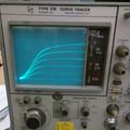
===Display and Readout=== | ===Display and Readout=== | ||
The display is large at 10 × 10 cm with an internal, parallax-free graticule. | The display is large at 10 × 10 cm with an internal, parallax-free graticule. | ||
Along the right side of the CRT is an alphanumeric readout which puts the important front panel settings | Along the right side of the CRT is an alphanumeric readout which puts the important front panel settings, where they can be photographed along with the displayed semiconductor curve. | ||
where they can be photographed along with the displayed semiconductor curve. | |||
This display is a complex unit of fiber optic light-guides driven by [[150-0048-01|incandescent lamps]] to provide alphabetic, numeric and Greek characters. | This display is a complex unit of fiber optic light-guides driven by [[150-0048-01|incandescent lamps]] to provide alphabetic, numeric and Greek characters. The same readout modules were used in the short-lived [[5030]]/[[5031]] scope series. | ||
The same readout modules were used in the short-lived [[5030]]/[[5031]] scope series. | Given the front panel settings, the display automatically calculates beta/div using a [[155-0005-00|set of Tek-made custom ICs]]. | ||
The 576 was designed before the [[7000-series scopes]], and by a different engineering group | |||
The 576 was designed before the [[7000-series scopes]], and by a different engineering group. | |||
Surprisingly, this fiber-optic unit has not proved to be the least bit troublesome, | Surprisingly, this fiber-optic unit has not proved to be the least bit troublesome, | ||
considering all of the [[150-0048-01|incandescent lamps]] required to implement the design. | considering all of the [[150-0048-01|incandescent lamps]] required to implement the design. | ||
| Line 594: | Line 111: | ||
The little brother tracer, the [[577]], introduced at a later date, does not have this feature. | The little brother tracer, the [[577]], introduced at a later date, does not have this feature. | ||
=== | ===Test Fixtures=== | ||
The interface connections to the | The interface connections to the test fixtures are made through the same style of blue Amphenol 26-xxx-xx connectors used in the plug-ins on the 500-series oscilloscope line. | ||
of blue | |||
* [[576 Standard Test Fixture]] | |||
* [[172|172 programmable test fixture]] | |||
* [[176|176 high-current test fixture]] | |||
* [[HV_Diode_Test_Fixture|High Voltage Diode Test Fixture]] | |||
* [[067-0599-00|067-0599-00 calibration fixture]] | |||
The | ==Uses== | ||
The collector voltage can be swept from zero to 1500 V in four ranges. | |||
For the 75 V and higher ranges, a [[337-1194-02|plastic safety cover box]] must be installed in the test fixture and closed, otherwise a yellow warning light indicates that the collector voltage is disabled. | |||
Because so many used 576s do not come with [[337-1194-02|safety covers]], some users defeat the safety interlock mechanically or electrically, which is hazardous given the lethal voltages and currents the 576 is capable of producing. | |||
The instrument has uses other than displaying semiconductor curves. | The instrument has uses other than displaying semiconductor curves. | ||
The vertical system can be adjusted for high current sensitivities in the nanoamp region and with the availability of | The vertical system can be adjusted for high current sensitivities in the nanoamp region and with the availability of 1500 volts and DC operation vs. collector supply sweeping, can provide measurement of capacitor leakage currents that few other instruments can achieve. | ||
1500 volts and DC operation vs. collector supply sweeping, can provide measurement of capacitor leakage currents that few other instruments can achieve. | |||
This is handy for checking ceramic high voltage filter capacitors in defective supplies. | This is handy for checking ceramic high voltage filter capacitors in defective supplies. | ||
The 576 is capable of displaying curves for bipolar transistors, field-effect transistors, silicon-controlled rectifiers, | The 576 is capable of displaying curves for bipolar transistors, field-effect transistors, silicon-controlled rectifiers, triacs, diacs, diodes and rectifiers, zener diodes, tunnel diodes … nearly any semiconductor imaginable. | ||
triacs, diacs, diodes and rectifiers, zener diodes, tunnel diodes … nearly any semiconductor imaginable. | |||
If one constructs simple adaptors, the 576 can be used to check optocouplers and transistor arrays as well. | If one constructs simple adaptors, the 576 can be used to check optocouplers and transistor arrays as well. | ||
It is capable of pouring 20 amperes through a device up to a power level of 220 watts. | It is capable of pouring 20 amperes through a device up to a power level of 220 watts. | ||
The demise of the original 575 came in 1971 when the 575's companion 175 pulsed high-current unit was no longer sold, | The demise of the original 575 came in 1971 when the 575's companion 175 pulsed high-current unit was no longer sold, replaced by the 576 with its new 176 pulsed high-current adaptor. | ||
replaced by the 576 with its new 176 pulsed high-current adaptor. | |||
The 575 itself disappeared from the catalog about a year later. | The 575 itself disappeared from the catalog about a year later. | ||
Vacuum tubes can have their curves traced on a 576. | Vacuum tubes can have their curves traced on a 576. | ||
| Line 642: | Line 143: | ||
The Tektronix [[570]] (last sold around 1966) specializes in tube measurements | The Tektronix [[570]] (last sold around 1966) specializes in tube measurements | ||
and has a built-in heater supply for the tube under test, which makes the 570 convenient. | and has a built-in heater supply for the tube under test, which makes the 570 convenient. | ||
However, with a custom fixture, the 576 can make most, if not all, | However, with a custom fixture, the 576 can make most, if not all, of the same measurements that can be made on a 570. | ||
of the same measurements that can be made on a 570. | |||
The AC collector sweep mode is useful when one wants a single plot showing the behavior of a device with positive and negative | The AC collector sweep mode is useful when one wants a single plot showing the behavior of a device with positive and negative voltages. For example, a zener diode typically starts conducting at a few hundred millivolts in the positive direction, but has minimal reverse conduction until the zener voltage is reached, e.g. at 6.2 volts. | ||
voltages. For example, a zener diode typically starts conducting at a few hundred millivolts in the positive direction, | |||
but has minimal reverse conduction until the zener voltage is reached, e.g. | |||
On a different subject, it might be noted here that the introduction of the 576 marked the approximate time | On a different subject, it might be noted here that the introduction of the 576 marked the approximate time that Tektronix began moving from using the word “Type” in front of its model numbers (e.g. "Type 545B") to simply using the model number only. | ||
that Tektronix began moving from using the word “Type” in front of its model numbers (e.g. | |||
==Prices== | ==Prices== | ||
| Line 662: | Line 159: | ||
! Catalog price | ! Catalog price | ||
|align=right| $2,125 | |align=right| $2,125 | ||
|align=right| $18, | |align=right| $18,000 | ||
|- | |- | ||
! | ! In 2022 Dollars | ||
|align=right| $ | |align=right| $16,920 | ||
|align=right| $ | |align=right| $40,300 | ||
|} | |} | ||
When production ended with its final appearance in the 1990 catalog, the sales price of the 576 had escalated to a stunning $18,040, replaced by the [[370]] and [[371]] models selling for just a little bit more. | |||
The 576 now sells on eBay for anywhere from about $300 to over $2000, usually offered without the safety shield or any adaptors and often without the standard test fixture which sellers seem to enjoy offering separately. | |||
Many are sold with only the 176 pulsed high-current adaptor installed. | |||
The small transistor adaptors are selling for nearly their original catalog price. | |||
On average, the 576 is being sold on the used market for about 1/12 its last catalog price – or at about half the price when it first appeared in 1969. | |||
Overall, the instrument has held its value and popularity very well. | |||
==Pictures== | ==Pictures== | ||
| Line 692: | Line 189: | ||
Tek-576-GE-Diode.jpg | Trace for Ge Diode | Tek-576-GE-Diode.jpg | Trace for Ge Diode | ||
Tek-576-Zener.jpg | Trace for 27V Zener | Tek-576-Zener.jpg | Trace for 27V Zener | ||
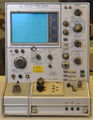
576 Front-panel controls, connectors and readout.png| Front-panel controls and connectors | |||
</gallery> | </gallery> | ||
| Line 698: | Line 195: | ||
<gallery> | <gallery> | ||
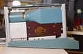
Tek 576 standard fixture internal.jpg|Standard Fixture, Internal View | Tek 576 standard fixture internal.jpg|Standard Fixture, Internal View | ||
Tek576_Readout 20240213.jpg | Detail of fiberoptic readout module | |||
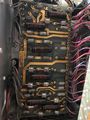
Tek 576 right internal.jpg|Right Internal View | Tek 576 right internal.jpg|Right Internal View | ||
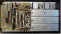
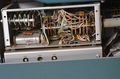
Tek 576 bottom internal.jpg|Bottom Internal View | Tek 576 bottom internal.jpg|Bottom Internal View | ||
| Line 708: | Line 205: | ||
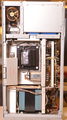
Tek 576 hvps.jpg|High-Voltage Power Supply | Tek 576 hvps.jpg|High-Voltage Power Supply | ||
</gallery> | </gallery> | ||
==Components== | |||
{{Parts|576}} | |||
[[Category:Curve tracers]] | [[Category:Curve tracers]] | ||
Latest revision as of 15:42, 18 August 2024

The Tektronix 576 is a curve tracer introduced in 1969. It was designed by Jim Knapton. It uses plug-in fixture modules such as the 172 and 176.
Unlike the 570, 575 and 7CT1N, the 576 (and also the 577) provides an AC collector sweep mode.
The 576 was the first product to use Tek-made ICs. The 576's display includes readout of current, voltage, Beta, and gm. The circuitry for calculating the scales based on the switch positions was designed by Mike Metcalf and implemented in custom ICs, e.g., 155-0005-00.
Key Specifications
| Collector Sweep Ranges |
|
|---|---|
| Collector Current Display | 0.1 μA/div to 2 A/div, 1−2−5 |
| Emitter Current Display | 0.1 nA/div to 2 mA/div, 1−2−5 |
| Collector Voltage Display | 5 mV/div to 200 V/div, 1−2−5 |
| Base Voltage Display | 5 mV/div to 2 V/div, 1−2−5 |
| Base Current Steps | 200 mA to 50 nA, 1−2−5 |
| Gate Voltage Steps | 50 mV to 2 V, 1−2−5 |
Note that these specifications are for the 576 Standard Test Fixture. See 576 Detailed Specifications for more data.
Links
- Curve Tracer Adapters
- Lazy Electrons 576 Restoration Page
- Tektronix 576 Curve Tracer System page at JAC Music (Includes a restoration article)
- Tek 576 @ amplifier.cd (including repair report, mostly in German)
- Tektronix 576, King of the curvetracers @ PA4TIM
- Dennis Tillman: An Inexpensive Vacuum Tube Curve Tracer Adapter for All Tektronix Semiconductor Curve Tracers
- Tek 576 by W2AEW @ YouTube - theory and measurement examples
- Zenwizard Studios - 576 Extensive Power Supply Rebuild and Calibration
- Zenwizard Studios - 576 Extensive Power Supply Rebuild and Calibration Minimal use of the Cal Fixture
- Zenwizard Studios - 176 Pulsed High Current Fixture
- Zenwizard Studios - Curve Tracer Basics
- Zenwizard Studios - Zen's Curve Tracer Buying Guide
- Tektronix 576 Curve Tracer - Part 1 @ Tinkering With Atkelar YouTube
- Tektronix 576 Curve Tracer - Part 2 @ Tinkering With Atkelar YouTube
- Tektronix 576 Curve Tracer - Part 3 @ Tinkering With Atkelar YouTube
Documents Referencing 576
| Document | Class | Title | Authors | Year | Links |
|---|---|---|---|---|---|
| Tekscope 1969 V1 N1 Feb 1969.pdf | Article | Curve Tracing Displays | 1969 | Curve tracers • 576 | |
| Tekscope 1969 V1 N1 Feb 1969.pdf | Article | A New Dimension in Curve Tracing | Jim Knapton • Jerrold Rogers | 1969 | 576 |
| Tekscope 1969 V1 N5 Oct 1969.pdf | Article | Troubleshooting the Sweep Ciruits | Charles Phillips | 1969 | 575 • 576 • Curve tracers |
| Tekscope 1971 V3 N3 May 1971.pdf | Article | Evaluating Digital IC Performance Using the 576 Curve Tracer | Jack Millay | 1971 | 576 |
| Tekscope 1972 V4 N3 May 1972.pdf | Article | Semiautomatic Testing with the Curve Tracer | Jack Millay | 1972 | 576 • 172 • Curve tracers |
| Tekscope 1975 V7 N3.pdf | Article | A Potpourri of Modifications and Service Hints | 1975 | 465 • 5L4N • 464 • 466 • 575 • 576 • 577 • TM504 | |
| 48W-3346-3.pdf | Brochure | Making the Correct Semiconductor Measurements Time After Time | 1982 | 576 • 172 • 176 • 577 • 178 • 5CT1N • 7CT1N | |
| 48w-5764.pdf | Brochure | Features Comparison of Tektronix Curve Tracers Versus HP4145A Semiconductor Parameter Analyzer (Tek internal) | Laurie Lawrence | 1984 | 576 • 577 • 176 • 177 • 178 |
Documents Referencing Curve tracers
| Document | Class | Title | Authors | Year | Links |
|---|---|---|---|---|---|
| 062-1009-00.pdf | Book | Measurement Concepts: Semiconductor Device Measurements | John Mulvey | 1969 | Curve tracers • Tunnel diodes |
| Tekscope 1969 V1 N1 Feb 1969.pdf | Article | Curve Tracing Displays | 1969 | Curve tracers • 576 | |
| Tekscope 1969 V1 N5 Oct 1969.pdf | Article | Troubleshooting the Sweep Ciruits | Charles Phillips | 1969 | 575 • 576 • Curve tracers |
| Tekscope 1972 V4 N3 May 1972.pdf | Article | Semiautomatic Testing with the Curve Tracer | Jack Millay | 1972 | 576 • 172 • Curve tracers |
| Tektronix Curve Tracers - Device Testing Techniques.pdf | Book | Tektronix Curve Tracers - Device Testing Techniques | 1985 | Curve tracers • Tunnel diodes |
Patents that may apply to 576
| Page | Title | Inventors | Filing date | Grant date | Links |
|---|---|---|---|---|---|
| Patent US 3453403A | Power selection device | Eldon Hoffman | 1966-08-18 | 1969-07-01 | 115 • 140 • 141 • 141A • 144 • 145 • 146 • 147 • 148 • 149 • 149A • 230 • 284 • 286 • 453 • 454 • 491 • 520A • 521A • 522 • 545B • 547 • 556 • 561B • 564B • 568 • 576 • 611 • 647A • 2101 • 2601 • 5030 • R5030 • 5031 • R5031 • 7503 • 7504 • 7704 • 7704A • 7904 • R7903 |
Construction
Except for the CRT, the 576 is all-solid-state.
It came out during the last four production years of the Type 575, which used the then-current 500-series technology of ceramic strips for circuit tie points.
The 576 used updated construction much in the same style as that of the 453 and 454 portable oscilloscopes, using printed circuit boards. In fact, the 576 and 453 began life at about the same time.
The only reason the Type 575 remained in production was because the 176 pulsed high-current fixture had not yet been developed for the 576, and the Type 575 coupled with its Type 175 pulsed high-current fixture filled that requirement for power semiconductors.
An interesting side note is that the 453 was introduced the same year as the 576; the 453A and 454A were introduced at the same time as the 176 pulsed high-current adaptor for the 576.
The 576 is unequaled in performance and durability. In physical volume, it is smaller than the Type 575, mostly due to a cabinet that slopes downward toward the back. Its sloping front panel and sloping “front porch” where the various adaptors are installed make it much a more comfortable instrument to use.
In addition, the 576 sports an internal graticule and a larger display area. Because of the power it is able to deliver to solid-state power semiconductors under test, it is a surprisingly heavy instrument for its smaller size, and despite its solid-state design, weighs in at 70½ pounds (32 kg) vs. the 66¼ pound (30 kg) weight of the Type 575.
The HV supply for the CRT uses a 120-0612-00, 120-0612-01, or 120-0612-03 transformer.
Display and Readout
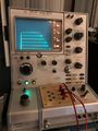
The display is large at 10 × 10 cm with an internal, parallax-free graticule. Along the right side of the CRT is an alphanumeric readout which puts the important front panel settings, where they can be photographed along with the displayed semiconductor curve.
This display is a complex unit of fiber optic light-guides driven by incandescent lamps to provide alphabetic, numeric and Greek characters. The same readout modules were used in the short-lived 5030/5031 scope series.
Given the front panel settings, the display automatically calculates beta/div using a set of Tek-made custom ICs.
The 576 was designed before the 7000-series scopes, and by a different engineering group. Surprisingly, this fiber-optic unit has not proved to be the least bit troublesome, considering all of the incandescent lamps required to implement the design. Wise operators will keep the display illumination at a lower level to prolong lamp life.
Display positioning in both the horizontal and vertical dimensions is via a switch which moves the beam a calibrated number of divisions and a potentiometer for fine control. The little brother tracer, the 577, introduced at a later date, does not have this feature.
Test Fixtures
The interface connections to the test fixtures are made through the same style of blue Amphenol 26-xxx-xx connectors used in the plug-ins on the 500-series oscilloscope line.
- 576 Standard Test Fixture
- 172 programmable test fixture
- 176 high-current test fixture
- High Voltage Diode Test Fixture
- 067-0599-00 calibration fixture
Uses
The collector voltage can be swept from zero to 1500 V in four ranges. For the 75 V and higher ranges, a plastic safety cover box must be installed in the test fixture and closed, otherwise a yellow warning light indicates that the collector voltage is disabled.
Because so many used 576s do not come with safety covers, some users defeat the safety interlock mechanically or electrically, which is hazardous given the lethal voltages and currents the 576 is capable of producing.
The instrument has uses other than displaying semiconductor curves. The vertical system can be adjusted for high current sensitivities in the nanoamp region and with the availability of 1500 volts and DC operation vs. collector supply sweeping, can provide measurement of capacitor leakage currents that few other instruments can achieve. This is handy for checking ceramic high voltage filter capacitors in defective supplies.
The 576 is capable of displaying curves for bipolar transistors, field-effect transistors, silicon-controlled rectifiers, triacs, diacs, diodes and rectifiers, zener diodes, tunnel diodes … nearly any semiconductor imaginable. If one constructs simple adaptors, the 576 can be used to check optocouplers and transistor arrays as well. It is capable of pouring 20 amperes through a device up to a power level of 220 watts.
The demise of the original 575 came in 1971 when the 575's companion 175 pulsed high-current unit was no longer sold, replaced by the 576 with its new 176 pulsed high-current adaptor. The 575 itself disappeared from the catalog about a year later.
Vacuum tubes can have their curves traced on a 576. This requires a fixture that provides the heater current to the tube under test. Pairs of tubes can be matched this way. Alternatively, the two triodes in a dual-triode can be compared. The Tektronix 570 (last sold around 1966) specializes in tube measurements and has a built-in heater supply for the tube under test, which makes the 570 convenient. However, with a custom fixture, the 576 can make most, if not all, of the same measurements that can be made on a 570.
The AC collector sweep mode is useful when one wants a single plot showing the behavior of a device with positive and negative voltages. For example, a zener diode typically starts conducting at a few hundred millivolts in the positive direction, but has minimal reverse conduction until the zener voltage is reached, e.g. at 6.2 volts.
On a different subject, it might be noted here that the introduction of the 576 marked the approximate time that Tektronix began moving from using the word “Type” in front of its model numbers (e.g. "Type 545B") to simply using the model number only.
Prices
| Year | 1969 | 1990 |
|---|---|---|
| Catalog price | $2,125 | $18,000 |
| In 2022 Dollars | $16,920 | $40,300 |
When production ended with its final appearance in the 1990 catalog, the sales price of the 576 had escalated to a stunning $18,040, replaced by the 370 and 371 models selling for just a little bit more.
The 576 now sells on eBay for anywhere from about $300 to over $2000, usually offered without the safety shield or any adaptors and often without the standard test fixture which sellers seem to enjoy offering separately.
Many are sold with only the 176 pulsed high-current adaptor installed. The small transistor adaptors are selling for nearly their original catalog price. On average, the 576 is being sold on the used market for about 1/12 its last catalog price – or at about half the price when it first appeared in 1969. Overall, the instrument has held its value and popularity very well.
Pictures
External
-
I-V Curves of a BJT at Low Collector Voltages
-
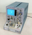
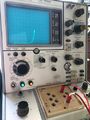
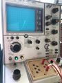
Tektronix 576
-
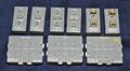
DUT Adapters
-
Front View
-
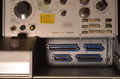
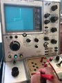
Plug-in Bay
-
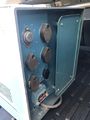
576 with clear plastic fixture cover
-
Rear
-
2N3094 NPN BJT Trace
-
Trace for Silicon Diode
-
Trace for Ge Diode
-
Trace for 27V Zener
-

Front-panel controls and connectors


Internal
-
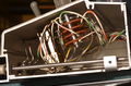
Standard Fixture, Internal View
-
Detail of fiberoptic readout module
-
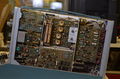
Right Internal View
-
Bottom Internal View
-
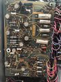
576 LV Regulator Board
-
576 LV Rectifier Board
-
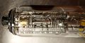
Tek 576 CRT gun
-
Left Internal
-
Max Peak Volts Switch and Series Resistors
-
High-Voltage Power Supply


Components
Some Parts Used in the 576
| Part | Part Number(s) | Class | Description | Used in |
|---|---|---|---|---|
| 120-0610-00 | 120-0610-00 | Discrete component | power transformer | 576 |
| 120-0612-00 | 120-0612-00 | Discrete component | high voltage transformer | 576 |
| 151-0261-00 | 151-0261-00 | Discrete component | dual PNP transistor | AM501 • AM502 • CG5001 • CG551AP • FG501 • FG502 • FG503 • OF150 • OF151 • OF152 • OF235 • OS261 • RM502A • R1140 • R5030 • R5031 • R7912 • 067-0679-00 • 067-0807-00 • 1101 • 1140A • 1141 • 1142 • 1350 • 145 • 1450 • 1480 • 1481 • 1482 • 1485 • 1501 • 1801 • 1900 • 1910 • 1980 • 213 • 26A1 • 26A2 • 2620 • 285 • 3A9 • 3A10 • 3S1 • 3S2 • 3S5 • 3S6 • 432 • 434 • 4501 • 454 • 4601 • 4602 • 4610 • 4612 • 4620 • 4632 • 4634 • 4701 • 475 • 492 • 492A • 492AP • 494 • 494P • 496 • 496P • 5A13N • 5A20N • 5A21N • 5A22N • 5A26 • 5L4N • 502A • 5030 • 5031 • 576 • 690SR • 7A22 • 7A29 • 7B51 • 7B71 • 7J20 • 7L5 • 7S11 • 7S12 • 7912AD |
| 155-0004-01 | 155-0004-01 | Monolithic integrated circuit | decoder | 576 |
| 155-0005-00 | 155-0005-00 | Monolithic integrated circuit | beta computer | 576 |
| 155-0006-01 | 155-0006-00 • 155-0006-01 | Monolithic integrated circuit | beta computer | 576 |
| 155-0007-01 | 155-0007-00 • 155-0007-01 | Monolithic integrated circuit | lamp driver | 576 |
| 155-0008-01 | 155-0008-00 • 155-0008-01 | Monolithic integrated circuit | lamp driver | 576 |