7904
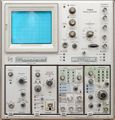
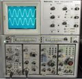
The Tektronix 7904 is a 500 MHz, non-storage 7000-series oscilloscope mainframe with four bays. It accepts two 7000-series vertical plug-ins and two 7000-series horizontal plug-ins. It was introduced in late 1971/early 1972 (Note 1). The successor model 7904A was introduced in 1984. There is also a rack-mount version, the R7903, albeit with only one horizontal bay.
Performance is largely determined by the plug-ins. The 7A19 vertical amplifier and 7B92 time base were introduced along with the 7904 to match the 500 MHz system bandwidth.
Design Staff of 7904 Project (from July 1971 Tekscope):
Val Garuts was project manager and developed the large signal amplifier circuit used in the horizontal and Z-axis amplifiers. Thor Hallen did the 7A19 plug-in and the vertical amplifier, and John McCormick the horizontal. The trigger and time base (7B92 plug-in) were done by Les Larson and Bill DeVey. Bill Peek worked on the Z-axis amplifier and auto-focus, with Hans Springer doing the mainframe interface and channel switching. Joe Burger's work on the power supply, coupled with Joel Swanno’s efforts in mechanical design, reduced the weight to only 30 pounds. Ken Hawken did the fine job on the CRT.
Key Specifications
| Bandwidth | 500 MHz |
|---|---|
| Fastest calibrated sweep | 500 ps/Div (with 7B92A, other time bases "uncalibrated for first 60 ns") |
| Acceleration voltage | 24 kV (+21 / -3 kV) |
| Calibrator | 7904: 4 mV, 40 mV, 400 mV, 4 V or 40 V (p-p) into 1 MΩ; 2 mV, 20 mV, 200 mV or 400 mV into 50 Ω; or 40 mA; selectable 1 kHz, ½ rep. rate of B Sweep Gate, or DC; 7904A: 4 mV to 4 V (p-p) in decade steps, 1 kHz; 40 mV to 400 mV into 50 Ω |
| Power consumption | 190 W |
| Weight | 13.5 kg (30 lbs) |
| CRT |
|
7904A differences
The 7904A (introduced in 1984) re-implements the vertical amplifier using Hypcon-packaged amplifier chips designed for the 7104, such as the 155-0178-00.
The 7904 had an elaborate 5-decade built-in calibrator with variable rate that was dropped from the 7904A. The rear remote control connector unique to early 7000-series scopes was dropped as well. In the 7904A, The Control Illumination switch moved to the rear panel, and the readout system gained a pulsed mode in which it is synchronized with the sweep instead of interrupting the display at random times. This pulsed mode is not compatible with all time base plug-ins (see manual p. 1-12).
Options
- Opt.2: X-Y delay compensation network
- Opt.3: Extra EMI shielding
- Opt.4: Maximum-brightness CRT with reduced area
- Opt.78: P11 phosphor
Operation
The 7904 has many modes of operation. One mode is called "Independent-Pairs Display" in the manual, where the input to the left vertical plug-in is displayed using the B horizontal time-base plug-in, and the input to the right vertical plug-in is displayed using the A horizontal time-base plug-in. This resembles the trace-slaving "ALT" mode that is produced by an 1A4 in a 547. Many other modes are available. It is possible to put vertical plug-ins in the horizontal slots for X-Y operation. It is even possible to put a horizontal plug-in in one of the vertical slots to produce a raster scan.
A special plug-in, the 7A21N, provides direct access to the deflection plates up to 1 GHz at an uncalibrated sensitivity of 4 V/Div. This plugin requires modifications to the mainframe to bypass the Y output amplifier (thus disabling readout and the other vertical plugin bay).
A rear-panel remote control connector has connections for single-sweep ready lamps, a reset button, and readout control.
Internals
The 7904 uses a switch-mode power supply and has no fan. It incorporates a 65 ns Y delay line. This delay is too short for some older time bases such as 7B53 to display the trigger event.
Thor Hallen designed the main vertical amplifier and the 7A19 plugin (Note 1). It used bridged T coils and the "ft doubler" circuit patented by Carl Battjes to achieve its bandwidth.
The 7904 makes extensive use of custom integrated circuits and hybrid circuits, inter alia, the 155-0064-00 470-ps output amplifier, 155-0022-00 analog multiplexer for channel switching, 155-0059-00 HF amplifier, 155-0095-01 and 155-0095-03 differential HF amplifiers, and 155-0067-02 SMPS controller.
The 7904A includes 155-0173-05, 155-0175-05 and 155-0178-05 amplifiers.
The signal path is completely differential and the internal signal wiring is 50 Ω coax. The CRT (154-0644-05) has distributed vertical deflection plates.
Prices
| Year | 1972 | 1976 | 1980 | 1984 | 1990 | |
|---|---|---|---|---|---|---|
| Model | 7904 | 7904 | 7904 | 7904A | 7904A | |
| Mainframe only | Catalog price | $2,900 | $4,100 | $6,265 | $8,810 | $12,750 |
| In 2022 Dollars | $19,500 | $20,300 | $21,400 | $23,800 | $27,400 | |
| Mainframe with 7A19, 7A19 Opt. 04, 7B92 |
Catalog price | $5,500 | $7,765 | $12,015 | $17,425 | $24,190 |
| In 2022 Dollars | $37,000 | $38,400 | $41,000 | $47,200 | $52,000 |
Links
- A Subnanosecond Realtime Oscilloscope, Tekscope Vol.3 No.4, July 1971
- 7904 Repair with Video
- Tek 7904 / 7904A @ amplifier.cd
- Repairing front panel buttons of Tektronix 7904 oscilloscope
- Tek 7904 / 7904A @ barrytech.com*
- Tektronix 7904 lab check in and LED MOD by Zenwizard Studios @ YouTube
Notes
- See 7A11 and John Addis, Good Engineering and Fast Vertical Amplifiers, in Jim Williams (Ed.), Analog Circuit Design: Art, Science and Personalities (1991), p.114, and Tektronix New Products 1972 brochure.
Pictures
7904 non-A
-
7904 (non-A) front
-
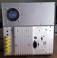
7904 rear
-
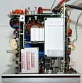
Left side. Left top: Vertical amplifier; left bottom: switch-mode power supply; right center: delay line; right bottom: plug-in bays
-
Right side. Top left: calibrator; bottom left: plug-in bays; top center: readout board; top right: Z amplifier
-
Right side detail. Left: calibrator; right: readout.
-
Plug-in backplane board front (left trigger selector piggyback board removed)
-
B Trigger selector piggyback board (A6)
-
Vertical interface piggyback board (A7). The two 155-0095-03 amplifiers (large metal cans) are used to select the signal from one vertical plug-in bay, and drive the delay line.
-
Plug-in backplane board rear
-
Backplane board sandwich seen from below
-
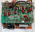
Horizontal (X) amplifier board
-
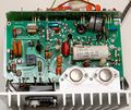
Vertical (Y) amplifier board
-
Z amplifier board
-
front-panel controls
-
7904 block diagram
Power Supply
-
7904 switchmode power supply, covers removed
-
View from right (as seen from front of instrument)
-
Primary side circuit board
-
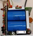
Primary side capacitors
-
Detail view of transformer from the side
-
Secondary side rectifier board
-
Secondary side post-regulator
7904A
-
7904A
-
7904A Rear
-
7904A Top with Horizontal Amplifier at top right
-
7904A Right with Z-axis on top right and 2nd Gen. Readout board at bottom right
-
7904A Left with Vertical Amplifier (top) and Vertical switch board (bottom)
-
7904A Topleft
-
7904A Closeup of Vertical amplifier
-
7904A Low-voltage Power Supply Schematic
-
7904A Horizontal and vertical amplifiers
CRTs used in the 7904
| Page | Part nos | Description | Designers | Used in |
|---|---|---|---|---|
| 154-0644-00 | 154-0644-00 • 154-0644-04 • 154-0644-05 • 154-0644-09 • 154-0893-05 | CRT with distributed deflection plates | Ken Hawken | 7704A • 7854 • 7904 • 7904A • R7903 |
CRTs used in the 7904A
| Page | Part nos | Description | Designers | Used in |
|---|---|---|---|---|
| 154-0644-00 | 154-0644-00 • 154-0644-04 • 154-0644-05 • 154-0644-09 • 154-0893-05 | CRT with distributed deflection plates | Ken Hawken | 7704A • 7854 • 7904 • 7904A • R7903 |
Custom ICs used in the 7904
Custom ICs used in the 7904A

