502: Difference between revisions
No edit summary |
No edit summary |
||
| (26 intermediate revisions by 4 users not shown) | |||
| Line 1: | Line 1: | ||
{{Oscilloscope Sidebar | | {{Oscilloscope Sidebar | ||
|manufacturer=Tektronix | |||
summary=1 MHz dual beam differential scope | | |series= | ||
image= | |model=502 | ||
caption=Tek 502 front (with Single Sweep Mod 104)| | |summary=1 MHz dual beam differential scope | ||
introduced=1958 | | |image=Tek 502 with x-y display.jpg | ||
discontinued=1973 | | |caption=Tek 502 front (with Single Sweep Mod 104) | ||
manuals= | |introduced=1958 | ||
* [[Media:IM-502-1.pdf|502 (early) Instruction]] | |discontinued=1973 | ||
* [[Media:070-090.pdf|502 (late) Instruction]] | |designers=Gary Vance | ||
* [[Media:070-382.pdf|502A Instruction]] | |manuals= | ||
'''502''' | |||
* [[Media:Tek 502a fcp sn31k-up june 1969.pdf | Tektronix 502A sn 31,000-up Factory Calibration Procedure, June 1969 | * [[Media:IM-502-1.pdf|502 (early) Instruction]] | ||
* [[Media:070-090.pdf|502 (late) Instruction]] | |||
'''502A''' | |||
* [[Media:070-382.pdf|502A Instruction]] | |||
* [[Media:070-0382-02.pdf|502A/RM502A (late) Instruction)]] | |||
'''Calibration''' | |||
* [[Media:Tek 502a fcp sn31k-up june 1969.pdf | Tektronix 502A sn 31,000-up Factory Calibration Procedure, June 1969]] | |||
* [[Media:Tek 502a cal outline.pdf|502A Calibration Outline]] | |||
}} | }} | ||
The '''Tektronix 502''' is a dual-beam oscilloscope [[introduced in 1958]], followed by the 502A in 1963. | The '''Tektronix 502''' is a dual-beam oscilloscope [[introduced in 1958]], followed by the 502A in 1963. There is also a rack-mount model, the RM502A. | ||
There is also a rack-mount model, the RM502A. | |||
Both beams have differential inputs. The horizontal deflection plates are common to both beams. | Both beams have differential inputs. The horizontal deflection plates are common to both beams. | ||
| Line 22: | Line 28: | ||
A recessed switch in the left side panel allows the upper beam amplifier to be connected to the horizontal deflection plates for single-beam X-Y operation, providing a differential X input with the same sensitivity as the Y channel. The upper beam is positioned off screen in this mode. | A recessed switch in the left side panel allows the upper beam amplifier to be connected to the horizontal deflection plates for single-beam X-Y operation, providing a differential X input with the same sensitivity as the Y channel. The upper beam is positioned off screen in this mode. | ||
If the combination of time base setting and magnification selector results in a sweep faster than 1 μs/div, the horizontal scale is not calibrated, and a lamp on the front panel lights up to remind the operator of that. | |||
{{BeginSpecs}} | {{BeginSpecs}} | ||
{{Spec | Deflection | 100 μV/cm to 20 V/cm, 1−2−5, ±3% }} | {{Spec | Deflection | 100 μV/cm to 20 V/cm, 1−2−5, ±3% }} | ||
| Line 32: | Line 39: | ||
{{spec | Weight | 23.6 kg (52lb) }} | {{spec | Weight | 23.6 kg (52lb) }} | ||
{{EndSpecs}} | {{EndSpecs}} | ||
==Links== | |||
{{Documents|Link=502}} | |||
{{Documents|Link=502A}} | |||
* [http://www.amplifier.cd/Test_Equipment/Tektronix/Tektronix_other/502A.htm Tektronix 502A] @ amplifier.cd (many internal pictures) | |||
* [https://youtu.be/0D-z6_M76Ls Tektronix 502A internals] @ youtube (German) | |||
==Prices== | ==Prices== | ||
| Line 49: | Line 62: | ||
|align=right| $1,265 | |align=right| $1,265 | ||
|- | |- | ||
! | ! In 2023 Dollars | ||
|align=right| $ | |align=right| $8,700 | ||
|align=right| $ | |align=right| $8,500 | ||
|align=right| $ | |align=right| $10,500 | ||
|align=right| $ | |align=right| $9,600 | ||
|- | |- | ||
|} | |} | ||
| Line 59: | Line 72: | ||
==Internals== | ==Internals== | ||
The −150 V supply uses a [[5651]] voltage reference tube as its reference. | |||
The 6.2 V<sub>DC</sub> heater supply for the tubes in the first stage differential amplifier is transistor-regulated. | |||
This heater supply uses the −150 V supply as its reference. | This heater supply uses the −150 V supply as its reference. | ||
There is no post-deflection acceleration. The CRT cathode voltage is −2.9 kV. | |||
The early 502 uses a single supply for the upper beam and lower beam CRT cathodes (HV transformer [[120-114]]). | The early 502 uses a single supply for the upper beam and lower beam CRT cathodes (HV transformer [[120-114]]). | ||
| Line 73: | Line 84: | ||
the two beams to be cancelled out in step 8 of the calibration procedure. | the two beams to be cancelled out in step 8 of the calibration procedure. | ||
Later 502A models have a solid state (plus [[nuvistor]]) input stage, | |||
a [[6DJ8]] as the deflection amplifier, and transistors as amplifiers and emitter followers (only in the newest version). | |||
The 502 has a 123 °F (50.5 °C) [[thermal cutoff]] switch. | |||
==Pictures== | ==Pictures== | ||
===502=== | ===502=== | ||
<gallery> | <gallery> | ||
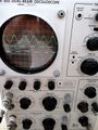
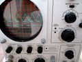
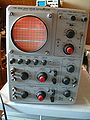
Tek 502 | Tek 502 with x-y display.jpg | 502 with (single-beam) X-Y display | ||
Tek 502 front fl.jpg | Tek_502_front.jpg | 502 Mod.104 (single sweep), front | ||
Tek 502 front fl.jpg | 502 Mod.104 (single sweep), front from lower left | |||
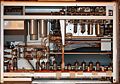
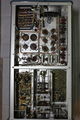
Tek 502 left.jpg|502 left | Tek 502 left.jpg | 502 left interior | ||
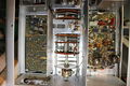
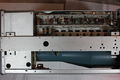
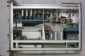
Tek 502 right.jpg|502 right | Tek 502 right.jpg | 502 right interior | ||
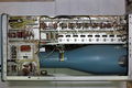
502 amplifier shock mount.jpg | rubber shock mount of amplifier sub-chassis | 502 amplifier shock mount.jpg | rubber shock mount of amplifier sub-chassis | ||
Tek 502 bottom.jpg|502 bottom | Tek 502 bottom.jpg | 502 bottom | ||
Tek 502 trace.jpg|502 trace | Tek 502 trace.jpg | 502 trace | ||
Tek 502 trace2.jpg|502 trace | Tek 502 trace2.jpg | 502 trace | ||
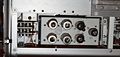
Tek 502 front panel wo knobs.jpg | 502 front panel without knobs | |||
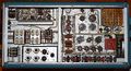
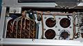
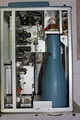
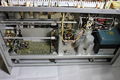
502 power supply operating.jpg | 502 power supply section in operation | |||
</gallery> | </gallery> | ||
| Line 127: | Line 142: | ||
===Diagrams=== | ===Diagrams=== | ||
<gallery> | <gallery> | ||
Tek 502a block.png|502A block diagram | Tek 502a block.png | 502A block diagram | ||
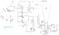
Tek-502a vert.png|502A vertical amplifier | Tek-502a vert.png | 502A vertical amplifier | ||
Tek 502 crt circuit.png|502 CRT circuit ( | Tek 502 crt circuit.png | Early 502 CRT circuit, [[120-114]] transformer (secondary transformer pin numbers incorrect) | ||
Tek 502a hvps.png|502A CRT circuit | Tek 502 crt circuit 070-090.png | Later 502 CRT circuit, [[120-150]] transformer | ||
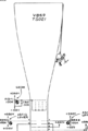
502-mountain-climber.png | Tek 502a hvps.png | 502A CRT circuit, [[120-150]] transformer | ||
502-mountain-climber.png | [[Tektronix Cartoons|Cartoon]] in schematic: Mountain Climber | |||
</gallery> | |||
===Applications=== | |||
<gallery> | |||
Tek 502A in Physiology Lab.jpg | Tek 502A in a Physiology lab | |||
</gallery> | </gallery> | ||
==Components== | |||
{{Parts|502}} | |||
{{Parts|502A}} | |||
[[Category:Dual beam scopes]] | [[Category:Dual beam scopes]] | ||
[[Category:Monolithic tube scopes]] | [[Category:Monolithic tube scopes]] | ||
Latest revision as of 15:20, 9 March 2024

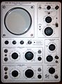
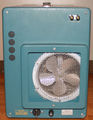
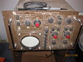
The Tektronix 502 is a dual-beam oscilloscope introduced in 1958, followed by the 502A in 1963. There is also a rack-mount model, the RM502A.
Both beams have differential inputs. The horizontal deflection plates are common to both beams.
Mod 104 on a 502 provides single sweep lockout. This feature is standard on the 502A, which also has beam finder switches for each channel.
A recessed switch in the left side panel allows the upper beam amplifier to be connected to the horizontal deflection plates for single-beam X-Y operation, providing a differential X input with the same sensitivity as the Y channel. The upper beam is positioned off screen in this mode.
If the combination of time base setting and magnification selector results in a sweep faster than 1 μs/div, the horizontal scale is not calibrated, and a lamp on the front panel lights up to remind the operator of that.
Key Specifications
| Deflection | 100 μV/cm to 20 V/cm, 1−2−5, ±3% |
|---|---|
| Bandwidth | 1 MHz @ 200 mV/cm and above; 400 kHz @ 50 mV/cm, 200 kHz @ 5 mV/cm, 100 kHz @ 200 μV/cm |
| CMRR | 502A: 40,000:1 @ 100 mV/cm and 1 kHz |
| Input impedance | 1 MΩ // 47 pF |
| Sweep | 1 μs/cm to 5 s/cm, 1−2−5, ±3%; magnifier ×2, ×5, ×10 or ×20 |
| CRT | Early 502: Type T60P2/T502P2/T5020P2; Late 502, 502A: Type T5021P2; (P1, P7 or P11 were available as options) 10 vertical and 10 horizontal 1 cm divisions 3 kV acceleration |
| Dimensions | 597 mm (23½") × 286 mm (11¼") × 381 mm (15") L×W×H |
| Weight | 23.6 kg (52lb) |
Links
Documents Referencing 502
- (no results)
Documents Referencing 502A
| Document | Class | Title | Authors | Year | Links |
|---|---|---|---|---|---|
| Service Scope 42 Feb 1967.pdf | Article | Simplify Waveform Measurements | 1967 | 502A |
- Tektronix 502A @ amplifier.cd (many internal pictures)
- Tektronix 502A internals @ youtube (German)
Prices
| Year | 1959 | 1961 | 1963 (A) | 1971 (A) |
|---|---|---|---|---|
| Catalog price | $825 | $825 | $1,050 | $1,265 |
| In 2023 Dollars | $8,700 | $8,500 | $10,500 | $9,600 |
Internals
The −150 V supply uses a 5651 voltage reference tube as its reference.
The 6.2 VDC heater supply for the tubes in the first stage differential amplifier is transistor-regulated. This heater supply uses the −150 V supply as its reference.
There is no post-deflection acceleration. The CRT cathode voltage is −2.9 kV.
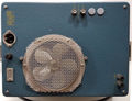
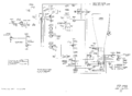
The early 502 uses a single supply for the upper beam and lower beam CRT cathodes (HV transformer 120-114). Later models (1959+, see 070-090) and the 502A have separate supplies for the two CRT cathodes (HV transformer 120-150). This improvement allows slight differences in horizontal CRT sensitivity between the two beams to be cancelled out in step 8 of the calibration procedure.
Later 502A models have a solid state (plus nuvistor) input stage, a 6DJ8 as the deflection amplifier, and transistors as amplifiers and emitter followers (only in the newest version).
The 502 has a 123 °F (50.5 °C) thermal cutoff switch.
Pictures
502
-

502 with (single-beam) X-Y display
-
502 Mod.104 (single sweep), front
-

502 Mod.104 (single sweep), front from lower left
-
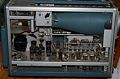
502 left interior
-
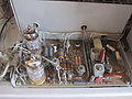
502 right interior
-
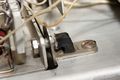
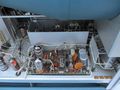
rubber shock mount of amplifier sub-chassis
-
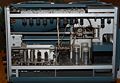
502 bottom
-
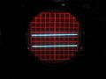
502 trace
-
502 trace
-
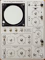
502 front panel without knobs
-
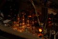
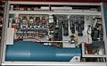
502 power supply section in operation


502A
-
502A
-

502A right internal
-
502A right
-
502A left
-
502A rear
-
Solid-state input stage with two 6DJ*
-
502A vertical amp sn 25,997 to 30,999


RM502A
-
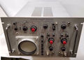
RM502A
-
RM502A rear
-
RM 502A
-
RM 502A display
-
RM 502A bottom
-
RM 502A transformer wiring
-
RM 502A top
-
RM 502A vibration-isolated vertical amp


Third version 502A, serial number ≥31,000
-
top side lower beam input amp and attenuator, bottom side of upper beam vert input board
-
late model RM502A
-
late model RM502A
-
late model RM502A
-
late model RM502A
-

late model RM502A
-
late model RM502A
-
late model RM502A


Diagrams
-
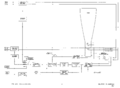
502A block diagram
-
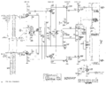
502A vertical amplifier
-
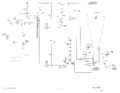
Early 502 CRT circuit, 120-114 transformer (secondary transformer pin numbers incorrect)
-
Later 502 CRT circuit, 120-150 transformer
-
502A CRT circuit, 120-150 transformer
-
Cartoon in schematic: Mountain Climber


Applications
-
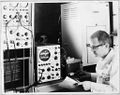
Tek 502A in a Physiology lab

Components
Some Parts Used in the 502
| Part | Part Number(s) | Class | Description | Used in |
|---|---|---|---|---|
| 120-117 | 120-117 | Discrete component | power transformer | 502 |
| 12AT7 | 154-0039-00 | Vacuum Tube (Dual Triode) | dual high-gain triode | 161 • 180 • 310 • 310A • 315 • 316 • 360 • 502 • 502A • 511A • 512 • 513 • 513D • 514 • 514AD • 514D • 516 • 524 • 529 • RM529 • 544 • 546 • 547 • 556 • 565 • 570 • 3A2 • 75 • 3A75 • 1M1 • A • B • C • G • H • K • L • ML • M • N • K • R • S • Z |
| 12AU7 | 154-041 • 154-0041-00 • 154-0287-00 | Vacuum Tube (Dual Triode) | dual medium-μ triode | 104 • 104A • 122 • 160 • 161 • 162 • 181 • 190 • 310 • 310A • 316 • 317 • 3C66 • 502 • 502A • 507 • 511A • 512 • 516 • 517 • 517A • 524 • 526 • 535 • 536 • 545 • 545A • 545B • 547 • 549 • 555 • 561 • 564 • 570 • 575 • 581 • 581A • 585 • 585A • C • D • E • N • Q • Hickok 1825 |
| 12B4 | 154-044 • 154-0044-00 | Vacuum Tube (Triode) | power triode | 126 • 310 • 310A • 316 • 317 • 502 • 502A • 524 • 526 • 541 • 541A • 535 • 535A • 545 • 545A • 546 • 547 • 570 • 549 • 551 • 555 • 513 • 581 • 581A • 585 • 585A |
| 2N301 | 151-0001-00 | Discrete component | germanium PNP power transistor | 502 • 502A |
| 5642 | 154-0051-00 • 154-0079-00 | Vacuum Tube (Diode) | directly-heated high-voltage rectifier | 310 • 310A • 316 • 317 • 360 • 453 • 502 • 502A • 503 • 504 • 506 • 513 • 515 • 516 • 524 • 529 • RM529 • 533 • 533A • 535 • 536 • 543 • 543A • 543B • 545 • 545A • 545B • 547 • 551 • 555 • 556 • 560 • 561 • 561A • 561S • 564 • 567 • 570 • 575 • 581 • 581A • 585 • 585A • 647 • 647A |
| 5651 | 154-052 • 154-0052-00 • 154-0288-00 | Gas Discharge Tube (Voltage regulator) | 87 V voltage reference | 128 • 160 • 310 • 310A • 502 • 503 • 504 • 511A • 512 • 516 • 517 • 524 • 526 • 531 • 531A • 535 • 536 • 541 • 541A • 543 • 543A • 543B • 545 • 545A • 545B • 570 • 549 • 581 • 581A • 585 • 585A |
| 5AR4 | 154-0168-00 | Vacuum Tube (Dual Rectifier) | dual rectifier | 502 • 502A • 160 |
| 6AL5 | 154-016 • 154-0016-00 • 154-0038-00 | Vacuum Tube (Dual Diode) | high-perveance dual diode | 163 • 181 • 190 • 1M1 • 310 • 310A • 315 • 316 • 317 • 3B1 • 3B1S • 3B2 • 3B3 • 3B5 • 502 • 502A • 503 • 511 • 511A • 512 • 516 • 517 • 517A • 524 • 526 • 535 • 535A • 545 • 545A • 549 • 551 • 565 • 570 • 581 • 581A • 585 • 585A • C • T • Telequipment D52 • Telequipment D56 • Telequipment S52 |
| 6AN8 | 154-078 • 154-0078-00 | Vacuum Tube (Triode/Pentode) | triode-pentode combo | 310 • 310A • 316 • 317 • 360 • 502 • 502A • 516 • 517 • 517A • 526 • 565 • 570 • 575 • N |
| 6AU6 | 154-0022-00 • 157-0073-00 • 157-0059-00 • 154-0284-00 | Vacuum Tube (Pentode) | RF pentode | 107 • 160 • 181 • 190 • 60 • 2A60 • 72 • 3A72 • 3C66 • 310 • 310A • 316 • 317 • 360 • 502 • 502A • 506 • 511 • 511A • 512 • 513 • 516 • 517 • 517A • 524 • 526 • 529 • RM529 • 531 • 531A • 535 • 536 • 545 • 545A • 546 • 547 • 549 • 555 • 561 • 561A • 561S • 564 • 565 • 567 • 570 • 575 • 581 • 581A • 585 • 585A • 80 • C • CA • Q |
| 6BW4 | 154-0119-00 | Vacuum Tube (Dual Diode) | dual diode | 126 • 502 • 502A • 524 • 575 |
| 6CZ5 | 154-0167-00 | Vacuum Tube (Pentode) | power pentode | 317 • 502 • 506 • 526 • 555 • 561 • 561A • 561S • 564 • 565 • 567 |
| 6DJ8 | 154-0187-00 • 154-0305-00 | Vacuum Tube (Dual Triode) | dual triode | 111 • 132 • 161 • 310A • 316 • 317 • 502 • 502A • 503 • 504 • 506 • 515 • 516 • 519 • 526 • 529 • RM529 • 533 • 535 • 536 • 543 • 544 • 545 • 545A • 545B • 546 • 547 • 549 • 555 • 556 • 561A • 561S • 564 • 565 • 567 • 581 • 581A • 585 • 585A • 661 • 1A4 • 1S1 • 60 • 2A60 • 63 • 2A63 • 67 • 2B67 • 3A1 • 3A1S • 3A2 • 3A3 • 3A6 • 3A7 • 72 • 3A72 • 75 • 3A75 • 4S2 • 51 • 3B1 • 3B1S • 3B2 • 3B3 • 3B4 • 3M1 • 3S76 • 3T77 • 3T77A • 9A1 • 9A2 • 1121 • 80 • 81 • 82 • 86 • B • O • W • Z • Telequipment D56 • Telequipment S32A • Telequipment D52 • S-311 • Telequipment TD51 • Telequipment S52 • Telequipment S51 • Telequipment Type A • TU-4 |
| 8056 | 154-0417-00 | Vacuum Tube (Triode) | low-voltage Nuvistor triode | 422 • 502 • W • 1S1 • 3A7 • 3S3 • 3T4 • 5T3 • 10A1 |
| T502 | 154-0144-00 • 154-144 • 154-0170-00 • 154-170 • 154-0172-00 • 154-172 • 154-0173-00 • 154-173 • 154-0269-00 • 154-269 • 154-0270-00 • 154-270 • 154-0271-00 • 154-271 • 154-0272-00 • 154-272 • 154-0273-00 • 154-273 • 154-0274-00 • 154-274 • 154-0275-00 • 154-275 • 154-0276-00 • 154-276 • 154-0348-00 | CRT | dual-beam CRT | 502 |