7704A: Difference between revisions
No edit summary |
No edit summary |
||
| (41 intermediate revisions by 9 users not shown) | |||
| Line 1: | Line 1: | ||
{{Oscilloscope Sidebar| | {{Oscilloscope Sidebar | ||
|manufacturer=Tektronix | |||
image=Tek | |series=7000-series scopes | ||
caption=7704A | |model= 7704A | ||
introduced= | |summary=200 MHz non-storage mainframe | ||
discontinued=1987 | | |image=Tek 7704a trace.jpg | ||
|caption=Tektronix 7704A | |||
manuals= | |introduced=1972 | ||
* [ | |discontinued=1987 | ||
|designers=Luis Navarro;Bob Shand;Bill Lukens;Jim Cavoretto;Bill Markwart;Dave Hoskins;Bill Gordon;Phil Lloyd;Dick Swanson;Larry Pearson | |||
|manuals= | |||
* [[Media:070-1260-00.pdf|Tektronix 7704A Manual]] | |||
* [[Media:070-1402-00.pdf|7704A Operators, Revs up to 1977]] | |||
}} | }} | ||
The '''Tektronix 7704A''' is a modular oscilloscope in the [[7000-series_scopes|7000 series]] | The '''Tektronix 7704A''' is a modular oscilloscope in the [[7000-series_scopes|7000 series]] that takes two [[7000-series_plug-ins#Vertical plug-ins|7000-series vertical plug-ins]] and two [[7000-series_plug-ins#Horizontal plug-ins|7000-series horizontal plug-ins]]. | ||
that takes two [[7000-series_plug-ins#Vertical plug-ins|7000-series vertical plug-ins]] | |||
and two [[7000-series_plug-ins#Horizontal plug-ins|7000-series horizontal plug-ins]]. | |||
The 7704A followed the [[7704]], improving bandwidth to 200 MHz (regular model, optimized | The 7704A followed the [[7704]] in 1972, improving bandwidth from 150 to 200 MHz (regular model, optimized for transient response) or 250 MHz (option 9, bandwidth-optimized). The rack-mount version continued to be based on the predecessor and was consequently just named [[R7704]]. | ||
for transient response) or 250 MHz (option 9, bandwidth-optimized). | |||
The 7704A has a special modular construction. At the bottom is the "acquisition unit", | The 7704A has a special modular construction. At the bottom is the "A7704 acquisition unit", which contains the power supply, plug-in slots, and main interface board. | ||
which contains the power supply, plug-in slots, and main interface board. On top is | On top is the "D7704 display unit", which contains the CRT, HV power supply, and output amplifiers for driving the deflection plates of the CRT. | ||
the "display unit", which contains the CRT, HV power supply, and output amplifiers for | These units detach. A large multi-pin connector passes signals and power from the acquisition unit to the display unit. | ||
driving the deflection plates of the CRT. These units detach. | It is important not to damage this connector when assembling or disassembling the units. | ||
passes signals and power from the acquisition unit to the display unit. It is important | |||
not to damage this connector when assembling or disassembling the units. | |||
An optional component, the [[P7001]] Processing Unit, can be added to a 7704A between the acquisition unit and the display unit. The Acquisition Unit of the 7704A, the P7001 Processor, and the Display Unit of the 7704A are connected by the Acquisition-Processor-Display (APD) Interface shown below. | An optional component, the [[P7001]] Processing Unit, can be added to a 7704A between the acquisition unit and the display unit. | ||
The Acquisition Unit of the 7704A, the P7001 Processor, and the Display Unit of the 7704A are connected by the Acquisition-Processor-Display (APD) Interface shown below. | |||
According to [[Media:Tekscope_1972_V4_N3_May_1972.pdf|Tekscope May 1972]], <blockquote> | |||
[[Luis Navarro]] was responsible for the electrical part of the project. [[Bill Lukens]] designed the low- and high-voltage power supplies, [[Jim Cavoretto]] did the vertical amplifier, and [[Bill Markwart]] the CRT readout. [[Bob Shand]] was responsible for the mechanical design, with [[Dave Hoskins]] and [[Bill Gordon]] doing the A7704 Acquisition Unit, [[Phil Lloyd]] the D7704 Display Unit, and [[Dick Swanson]] and [[Larry Pearson]] the interconnect system. | |||
</blockquote> | |||
{{BeginSpecs}} | |||
{{Spec | Fastest cal. sweep | 2 ns/Div }} | |||
{{Spec | Bandwidth | 200 MHz (with [[7A19]]) }} | |||
{{Spec | Calibrator | 4 mV to 40 V in decade steps, 2/20/200/400 mV into 50 Ω, 40 mA; 1 kHz }} | |||
{{Spec | Outputs | Vertical Signal Out (25 mV/Div, 60 MHz), +Sawtooth, +Gate, Cal, camera power, probe power }} | |||
{{Spec | Acceleration voltage | 24 kV }} | |||
{{Spec | Power | 90-132 V or 180-264 V, 48-440 Hz, 180 W max. }} | |||
{{Spec | Weight | 13.6 kg (30 lbs) }} | |||
{{Spec | Size | 34.5 cm × 30.5 cm × 57.7 cm (H×W×L) }} | |||
{{Spec | Options | | |||
* Option 1: No Readout | |||
* Option 3: Extra EMI shielding | |||
* Option 4: Reduced scan CRT (4x5 cm graticule) | |||
* Option 7: Deletes signals out (Vertical signal out, +Sawtooth, +Gate, Z-axis in, remote reset input). Readout always free-running. | |||
* Option 8: Phosphor change (P11, blue) | |||
* Option 9: Extended bandwidth (250 MHz, trades pulse response) | |||
}} | |||
{{EndSpecs}} | |||
==Links== | ==Links== | ||
* [http://amplifier.cd/Test_Equipment/Tektronix/Tektronix_7000_series_mainframe/7704A.htm 7704A page at amplifier.cd (with repair report, German)] / [https://translate.google.com/translate?sl=auto&tl=en&js=y&prev=_t&hl=en&ie=UTF-8&u=http%3A%2F%2Famplifier.cd%2FTest_Equipment%2FTektronix%2FTektronix_7000_series_mainframe%2F7704A.htm translated] | * [http://amplifier.cd/Test_Equipment/Tektronix/Tektronix_7000_series_mainframe/7704A.htm 7704A page at amplifier.cd (with repair report, German)] / [https://translate.google.com/translate?sl=auto&tl=en&js=y&prev=_t&hl=en&ie=UTF-8&u=http%3A%2F%2Famplifier.cd%2FTest_Equipment%2FTektronix%2FTektronix_7000_series_mainframe%2F7704A.htm translated] | ||
* [https://m.youtube.com/watch?v=Hz-gF_XSj9w 7704A demo @ YouTube] | |||
* [https://www.youtube.com/watch?v=16QHePfnkHk Zenwizard Studios - Tektronix 7704A Calibration] | |||
{{Documents|Link=7704A}} | |||
{{PatentLinks|7704A}} | |||
==Internals== | |||
The vertical amplifier in the 7704A uses the [[155-0077-00]] hybrid. | |||
In the 7704A, the [[7000 series readout system|readout board]] is located behind a back panel carrying two [[LEMO S-series connector]]s for probe power. This placement was intended to allow easy retrofitting of a readout board into an Option 1 instrument, however, the readout board is not a plug-in card − several cables have to be attached to the board. | |||
The 7704A SMPS uses a custom Tek chip ([[155-0067-02]]) to implement the control functions. For the initial start of the SMPS oscillator on power-up, early 7704As use a diac and later 7704As use a unijunction transistor in the starter circuit. | |||
==Pictures== | ==Pictures== | ||
<gallery> | <gallery> | ||
Tek 7704a trace.jpg | 7704A displaying a trace | |||
Tek 7704a 7a26 7b92a trace.jpg | 7704A displaying a trace | |||
Tek 7704A 1.jpg | 7704A | |||
USA Tektronix 7704A Front0.jpg | 7704A | |||
Tek-7704a-7D01.jpg | 7704A + [[7D01]] (from advertisement) | |||
Tek-7704a-manual.jpg | 7704A picture from manual | |||
P7001 apd interconnect.jpg | APD Interface | |||
Tek-7704A-Interconnect-1.jpg | Interconnect plug in normal position | |||
Tek-7704A-Interconnect-2.jpg | Interconnect plug on storage fixture | |||
Tek 7704a p7001 1.jpg | 7704A with [[P7001]] | |||
Tek 7704a rear1.jpg | 7704A rear | |||
Tek 7704a rear2.jpg | 7704A rear | |||
Tek 7704a rear3.jpg | 7704A rear | |||
Tek 7704a rise 1ns per div.jpg | 7704A Mod 9 rise time with [[7A29]] is 1.25 ns. Sweep was adjusted for exactly 1 ns / div using 1 GHz reference. | |||
</gallery> | </gallery> | ||
==Components== | |||
{{Parts|7704A}} | |||
{{Custom ICs|7000 series readout system}} | |||
[[Category:7000 series non-storage mainframes]] | [[Category:7000 series non-storage mainframes]] | ||
Latest revision as of 02:40, 18 June 2024
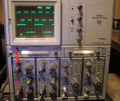
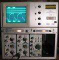
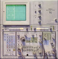
The Tektronix 7704A is a modular oscilloscope in the 7000 series that takes two 7000-series vertical plug-ins and two 7000-series horizontal plug-ins.
The 7704A followed the 7704 in 1972, improving bandwidth from 150 to 200 MHz (regular model, optimized for transient response) or 250 MHz (option 9, bandwidth-optimized). The rack-mount version continued to be based on the predecessor and was consequently just named R7704.
The 7704A has a special modular construction. At the bottom is the "A7704 acquisition unit", which contains the power supply, plug-in slots, and main interface board. On top is the "D7704 display unit", which contains the CRT, HV power supply, and output amplifiers for driving the deflection plates of the CRT. These units detach. A large multi-pin connector passes signals and power from the acquisition unit to the display unit. It is important not to damage this connector when assembling or disassembling the units.
An optional component, the P7001 Processing Unit, can be added to a 7704A between the acquisition unit and the display unit. The Acquisition Unit of the 7704A, the P7001 Processor, and the Display Unit of the 7704A are connected by the Acquisition-Processor-Display (APD) Interface shown below.
According to Tekscope May 1972,
Luis Navarro was responsible for the electrical part of the project. Bill Lukens designed the low- and high-voltage power supplies, Jim Cavoretto did the vertical amplifier, and Bill Markwart the CRT readout. Bob Shand was responsible for the mechanical design, with Dave Hoskins and Bill Gordon doing the A7704 Acquisition Unit, Phil Lloyd the D7704 Display Unit, and Dick Swanson and Larry Pearson the interconnect system.
Key Specifications
| Fastest cal. sweep | 2 ns/Div |
|---|---|
| Bandwidth | 200 MHz (with 7A19) |
| Calibrator | 4 mV to 40 V in decade steps, 2/20/200/400 mV into 50 Ω, 40 mA; 1 kHz |
| Outputs | Vertical Signal Out (25 mV/Div, 60 MHz), +Sawtooth, +Gate, Cal, camera power, probe power |
| Acceleration voltage | 24 kV |
| Power | 90-132 V or 180-264 V, 48-440 Hz, 180 W max. |
| Weight | 13.6 kg (30 lbs) |
| Size | 34.5 cm × 30.5 cm × 57.7 cm (H×W×L) |
| Options |
|
Links
- 7704A page at amplifier.cd (with repair report, German) / translated
- 7704A demo @ YouTube
- Zenwizard Studios - Tektronix 7704A Calibration
Documents Referencing 7704A
| Document | Class | Title | Authors | Year | Links |
|---|---|---|---|---|---|
| Tekscope 1972 V4 N3 May 1972.pdf | Article | The 7704A – Extended Performance Plus Modularity | Luis Navarro • Bob Shand | 1972 | 7704A |
| 7000 series brochure March 1973.pdf | Brochure | 7000 series brochure, March 1973 | 1973 | 7A11 • 7A12 • 7A13 • 7A14 • 7A15A • 7A16A • 7A17 • 7A18 • 7A19 • 7A21N • 7A22 • 7B50 • 7B53A • 7B70 • 7B71 • 7B92 • 7CT1N • 7D11 • 7D13 • 7D14 • 7D15 • 7M11 • 7L12 • 7S11 • 7S12 • 7T11 • 7704A • R7704 • 7904 • R7903 • 7603 • R7603 • 7403N • R7403N • 7313 • R7313 • 7613 • R7613 • 7623 • R7623 • P7001 | |
| Tekscope 1973 V5 N2 Mar 1973.pdf | Article | The Oscilloscope with Computing Power | Hiro Moriyasu • Luis Navarro • Jack Gilmore • Bruce Hamilton | 1973 | 7704A • P7001 |
| RISOM2873.pdf | Article | Improvement of the Bandwidth of the Transient Digitizers in the LIDAR Thomson Scattering Diagnostic on JET | Erik Kristensen | 1990 | 7912AD • 7A29 • 7704A • 7S12 • S-6 • S-52 |
Patents that may apply to 7704A
| Page | Title | Inventors | Filing date | Grant date | Links |
|---|---|---|---|---|---|
| Patent US 3453403A | Power selection device | Eldon Hoffman | 1966-08-18 | 1969-07-01 | 115 • 140 • 141 • 141A • 144 • 145 • 146 • 147 • 148 • 149 • 149A • 230 • 284 • 286 • 453 • 454 • 491 • 520A • 521A • 522 • 545B • 547 • 556 • 561B • 564B • 568 • 576 • 611 • 647A • 2101 • 2601 • 5030 • R5030 • 5031 • R5031 • 7503 • 7504 • 7704 • 7704A • 7904 • R7903 |
Internals
The vertical amplifier in the 7704A uses the 155-0077-00 hybrid.
In the 7704A, the readout board is located behind a back panel carrying two LEMO S-series connectors for probe power. This placement was intended to allow easy retrofitting of a readout board into an Option 1 instrument, however, the readout board is not a plug-in card − several cables have to be attached to the board.
The 7704A SMPS uses a custom Tek chip (155-0067-02) to implement the control functions. For the initial start of the SMPS oscillator on power-up, early 7704As use a diac and later 7704As use a unijunction transistor in the starter circuit.
Pictures
-
7704A displaying a trace
-
7704A displaying a trace
-
7704A
-
7704A
-
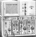
7704A + 7D01 (from advertisement)
-
7704A picture from manual
-
APD Interface
-
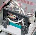
Interconnect plug in normal position
-
Interconnect plug on storage fixture
-
7704A with P7001
-
7704A rear
-
7704A rear
-
7704A rear
-
7704A Mod 9 rise time with 7A29 is 1.25 ns. Sweep was adjusted for exactly 1 ns / div using 1 GHz reference.
Components
Some Parts Used in the 7704A

