FG5010: Difference between revisions
No edit summary |
No edit summary |
||
| (5 intermediate revisions by 2 users not shown) | |||
| Line 1: | Line 1: | ||
{{TM5000 | mfg=Tektronix | type=FG5010 | function=20 MHz function generator | {{TM5000 | ||
|class=function generator | |||
|mfg=Tektronix | |||
|type=FG5010 | |||
|function=20 MHz function generator | |||
|image=Tek fg5010 front.jpg | |||
|introduced=1982 | |||
|discontinued=1991 | |||
|designers=Dennis Hall;Steve Rice;Tom Hill;Bob Beville | |||
|manuals= | |||
* [[Media:070-3467-01.pdf | Tek FG5010 Manual Rev. 01, 1982]] (with schematics) | * [[Media:070-3467-01.pdf | Tek FG5010 Manual Rev. 01, 1982]] (with schematics) | ||
* ''later manual covering CPU Rev.01 needed'' | * ''later manual covering CPU Rev.01 needed'' | ||
| Line 10: | Line 19: | ||
{{ROM Images}} | {{ROM Images}} | ||
}} | }} | ||
{{ | According to [[Bob Beville]]'s [[Media:Beville-Memoirs-02142019.pdf|memoirs]], | ||
<blockquote> | |||
[In 1977 I was] in the FG5010 Function Generator design group. [[Dennis Hall]], manager; [[Steve Rice]], software, ramp/saw tooth/sinewave circuits; [[Tom Hill]], output circuits; me, N Burst circuits, configuration and interface/motherboard. | |||
All submitted their circuit’s inputs and outputs to me and what-connected-to-what. I arranged the motherboard connector assignments and some motherboard layout paths. The product became very crammed. | |||
</blockquote> | |||
{{BeginSpecs}} | |||
{{Spec | Frequency Range | 2 mHz to 20 MHz}} | |||
{{Spec | Waveshapes | Sine, Square, Triangle, Pulse, Ramp}} | |||
{{Spec | Output | max. 20 V<sub>p-p</sub> (OC)}} | |||
{{Spec | Risetime | 10 ns}} | |||
{{Spec | Modulation | External AM, FM, VCF}} | |||
{{Spec | Symmetry | 10 to 90 %}} | |||
{{Spec | Modes | Trigger, Gate, Counted Burst}} | |||
{{Spec | Frequency Sweep | 1000:1}} | |||
{{EndSpecs}} | |||
==Links== | ==Links== | ||
Latest revision as of 03:00, 5 November 2024
The Tektronix FG5010 is a 20 MHz function generator plug-in for the TM5000 system. According to Bob Beville's memoirs,
[In 1977 I was] in the FG5010 Function Generator design group. Dennis Hall, manager; Steve Rice, software, ramp/saw tooth/sinewave circuits; Tom Hill, output circuits; me, N Burst circuits, configuration and interface/motherboard.
All submitted their circuit’s inputs and outputs to me and what-connected-to-what. I arranged the motherboard connector assignments and some motherboard layout paths. The product became very crammed.
Key Specifications
| Frequency Range | 2 mHz to 20 MHz |
|---|---|
| Waveshapes | Sine, Square, Triangle, Pulse, Ramp |
| Output | max. 20 Vp-p (OC) |
| Risetime | 10 ns |
| Modulation | External AM, FM, VCF |
| Symmetry | 10 to 90 % |
| Modes | Trigger, Gate, Counted Burst |
| Frequency Sweep | 1000:1 |
Links
- Checking out a Tektronix FG5010 @ YouTube
Documents Referencing FG5010
Internals
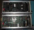
The original version (1982) had three Mostek MK36000 8K×8 mask ROMs (U1540 $A000-$BFFF, U1440 $C000-$DFFF, U1332 $E000-$FFFF). Code updates could be accommodated via a 2716 "patch" EPROM (U1640, 160-1712-xx) and a Signetics 82S107 "Field Programmable ROM Patch (16X48X8)" (U1420).
The updated CPU board (Rev.01, ca. 1985) replaced this complex arrangement with a single EPROM (160-1091-xx, 160-4971-00).
Pictures
-
-
-
-
-
right internal
-
left internal
-
upper: new CPU Board REV: 01, lower old CPU Board REV:00


