7S12: Difference between revisions
No edit summary |
No edit summary |
||
| Line 39: | Line 39: | ||
* Jitter: < 20 ps | * Jitter: < 20 ps | ||
}} | }} | ||
{{Spec | Sweep modes | | {{Spec | Sweep modes | free-running, single, manual, external input | ||
}} | }} | ||
{{Spec | Air Dielectric Range | | {{Spec | Air Dielectric Range | | ||
* 15 m (49 ft) | * 15 m (49 ft) | ||
* 150 m (490 ft) | * 150 m (490 ft) | ||
* 1500 m (4900 ft) | * 1500 m (4900 ft) | ||
Revision as of 13:36, 21 June 2024

The Tektronix 7S12 is a Time Domain Reflectometer / Sampler plug-in for 7000-series scopes. It occupies two mainframe plug-in bays (one vertical, one horizontal).
The 7S12 has two bays for S-series plug-in modules ("heads"). The right bay accepts a pulse generator or a trigger recognizer plug-in, whereas the left bay accepts a sampling plug-in.
The typical configuration is to have an S-6 on the left and an S-52 on the right for time domain reflectometry, or a sampling head like the S-4 on the left and an S-53 on the right as a generic sampler.
The 7S12 can also control an optional 7S11 through its left side contacts, adding a second input channel.
Y axis can be scaled in voltage (mV) or reflection coefficient (ρ) units, X axis in time or distance.
Key Specifications
| Sweep modes | Single / Repetitive / Manual / External input |
|---|---|
| With S-6 and S-52 |
|
| With S-5 and S-54 |
|
| Sweep modes | free-running, single, manual, external input |
| Air Dielectric Range |
|
| Weight | 2.13 kg (4.7 lbs) |
Links
- Tektronix 062-1244-00: Time-Domain Reflectometry Measurement Concepts, James A. Strickland, 1969. pages.
- Service Scope No. 45, August 1967 - Time-Domain Reflectometry Theory
- Tek 7S12 @ amplifier.cd
- Tek 7S12 @ barrytech.com
- Evaluation of 7S12 performance (video)
- 7S12 extender board by Dave Partridge
Documents Referencing 7S12
| Document | Class | Title | Authors | Year | Links |
|---|---|---|---|---|---|
| 7000 series brochure March 1973.pdf | Brochure | 7000 series brochure, March 1973 | 1973 | 7A11 • 7A12 • 7A13 • 7A14 • 7A15A • 7A16A • 7A17 • 7A18 • 7A19 • 7A21N • 7A22 • 7B50 • 7B53A • 7B70 • 7B71 • 7B92 • 7CT1N • 7D11 • 7D13 • 7D14 • 7D15 • 7M11 • 7L12 • 7S11 • 7S12 • 7T11 • 7704A • R7704 • 7904 • R7903 • 7603 • R7603 • 7403N • R7403N • 7313 • R7313 • 7613 • R7613 • 7623 • R7623 • P7001 | |
| 42W-5334.pdf | Application Note | Automated TDR Testing Made Easy with the 7854 Oscilloscope/7S12 Sampler Plug-In | 1983 | 7854 • 7S12 | |
| Rochester LLE Review Volume 25.pdf | Article | Computerized, Wide-Bandwidth, Multichannel, Soft X-Ray Diode Spectrometer for High Density Plasma Diagnosis | 1985 | 7S12 • S-52 • S-6 • LM7912 • LM7912A • 7912DPO | |
| RISOM2873.pdf | Article | Improvement of the Bandwidth of the Transient Digitizers in the LIDAR Thomson Scattering Diagnostic on JET | Erik Kristensen | 1990 | 7912AD • 7A29 • 7704A • 7S12 • S-6 • S-52 |
Patents that may apply to 7S12
Pictures
-
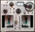
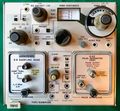
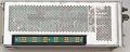
Front view without sampling head plug-ins
-
-
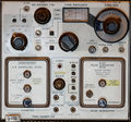
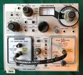
7S12 TDR "self portrait" in 7613 storage mainframe
-
-
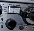
Metric dial tape
-
-
-


Inside
-
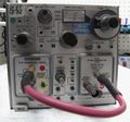
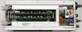
Left side
-
Left side with cover. Side contacts to interface 7S11 are exposed.
-
Right side
-
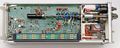
Top view
-
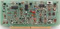
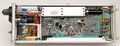
Horizontal board
-
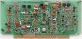
Vertical board


Measurements
TDR
-
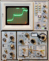
TDR "Self Portrait" — pulse reflected on S-6 "through" path (approx. 120 ps one way)
-
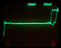
7S12 displaying the incident pulse from an S-52 (nom. < 25 ps) through an S-6 head (nom. < 30 ps). Displayed rise time ~35 ps confirms spec.
-
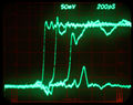
7S12/S-6/S-52 displaying pulse reflection from ~ 5 in semi-rigid SMA cable. Stored display of two traces. Left trace: cable only, right trace: cable plus SMA-to-BNC adapter (~ 25 mm)
-
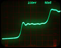
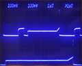
7S12/S-6/S-52 displaying reflected pulse from end of 5 in semi-rigid SMA cable. Stored display overlaying multiple traces, left to right: cable alone, SMA-to-BNC adapter added, BNC f-f adapter added, (cheap) 50 Ω terminator added.
-
Full pulse pattern of a 7S12/S-52 in real time (top trace) and sampled (bottom trace) shown simultaneously on 7844. 7S12 trace at slowest possible sweep.
-
S-52 pulse in real time (top trace) and sampled (bottom trace) shown simultaneously on 7844. Approximately equal time scales.


Probe rise times
-

-
-
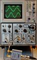
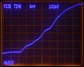
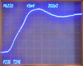
P6230 Rise time, no ground lead
-
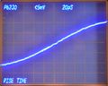
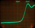
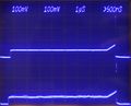
P6230 Rise time, no ground lead, enlarged – 9.2 * 20 ps = 184 ps (equiv. to 1.9 GHz bandwidth)
-
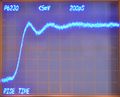
P6230 with "low inductance" ground lead – rise time 400 ps, bandwidth 875 MHz


